


Easy Way to install Proteus 7.6 SP4
[1] if you have a previous version of Proteus, you must first uninstall it.
[2] Download Proteus7.6 from Here.
[3] Download the license file and the Crack from Here.
[4] after downloading, open the Proteus 7.6SP4 Folder and select the setup.exe file as shown: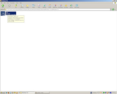
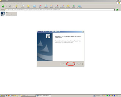
[5] Press Next
[6] select Yes:
 [7] Select the first option. then click Next :
 [8] if you didn't install it before, you will notice that there is no license file exist. if you installed it before you will automatically find the license. but ensure that it is valid and not expired. And if it is invalid, you must do the step in the notes bellow. So, press Next :
 [9] From the dialog appeared select browse for key file :
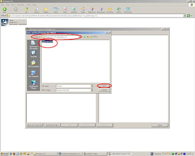
 [10] you will find the license file in the crack folder that you've downloaded at step[3] select the license file "Sonsivri" then select open:
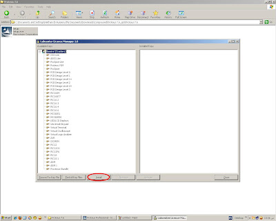
[11] Select install :
[12] a confirmation dialog will appear. select Yes :
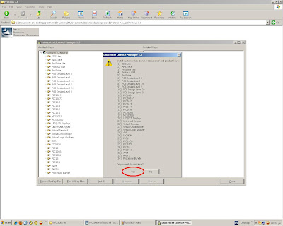
[13] you will see the items moved to the right side. So, select Close :
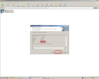
 [14] after ensuring that the Expiry date is 1/1/2030, select Next :
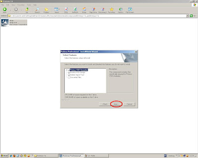
[15] Select Next :
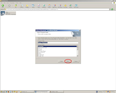
 [16] Then, Next:
[17] Then, Next:
[18] Now you are installing the program. So, be patient for a while :
 [19] after finishing installation, Select Finish :

Now we will show how to install the Crack :
[1] go to the crack folder you've downloaded at step [3] and copy the patch file:
 [2] Paste the file into the Program installation folder in program files:"C:\Program Files\Labcenter Electronics\Proteus 7 Professional"
 [3] Run the Patch file and press Patch :
Note: for windows Vista and windows 7 you must run it as an administrator by right click on the file and select "run as an administrator"
 [4] a message will appear asking for a missing file "ISIS.EXE". So, go to:"C:\Program Files\Labcenter Electronics\Proteus 7 Professional\BIN"
and point to the file:
 [5] another message asking for a missing file "82XX.DLL" so, go to"C:\Program Files\Labcenter Electronics\Proteus 7 Professional\MODELS"
and point to the file:
 [6] after patching done click Exit:
 [7] Now you have finished installing the program. to run it go to" Start Menu>>All Programs>>Proteus 7 Professional>> ISIS7 Professional "
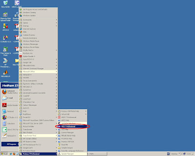
[2] Download Proteus7.6 from Here.
[3] Download the license file and the Crack from Here.
[4] after downloading, open the Proteus 7.6SP4 Folder and select the setup.exe file as shown:

[5] Press Next

[6] select Yes:
 [7] Select the first option. then click Next :
 [8] if you didn't install it before, you will notice that there is no license file exist. if you installed it before you will automatically find the license. but ensure that it is valid and not expired. And if it is invalid, you must do the step in the notes bellow. So, press Next :
 [9] From the dialog appeared select browse for key file :
 [10] you will find the license file in the crack folder that you've downloaded at step[3] select the license file "Sonsivri" then select open:
[11] Select install :

[12] a confirmation dialog will appear. select Yes :

[13] you will see the items moved to the right side. So, select Close :
 [14] after ensuring that the Expiry date is 1/1/2030, select Next :
[15] Select Next :
 [16] Then, Next:
[17] Then, Next:

[18] Now you are installing the program. So, be patient for a while :
 [19] after finishing installation, Select Finish :
Now we will show how to install the Crack :
[1] go to the crack folder you've downloaded at step [3] and copy the patch file:
 [2] Paste the file into the Program installation folder in program files:"C:\Program Files\Labcenter Electronics\Proteus 7 Professional"
 [3] Run the Patch file and press Patch :
Note: for windows Vista and windows 7 you must run it as an administrator by right click on the file and select "run as an administrator"
- Also if you have any antivirus software so disable this first and then open the Patch file .
 [4] a message will appear asking for a missing file "ISIS.EXE". So, go to:"C:\Program Files\Labcenter Electronics\Proteus 7 Professional\BIN"
and point to the file:
 [5] another message asking for a missing file "82XX.DLL" so, go to"C:\Program Files\Labcenter Electronics\Proteus 7 Professional\MODELS"
and point to the file:
 [6] after patching done click Exit:
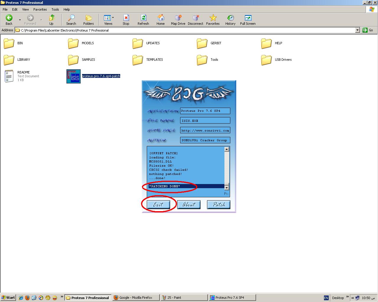 [7] Now you have finished installing the program. to run it go to" Start Menu>>All Programs>>Proteus 7 Professional>> ISIS7 Professional "
___________
Notes:
if you installed it before with an invalid License file you can do this step after finishing installing the program and crack :
go to " Start Menu>>All Programs>>Proteus 7 Professional>> Licence Manager"
and do the steps from [9] to [13].
if you installed it before with an invalid License file you can do this step after finishing installing the program and crack :
go to " Start Menu>>All Programs>>Proteus 7 Professional>> Licence Manager"
and do the steps from [9] to [13].
Thanks u for learning ......
Electronics Lab Created By Muhammad Irfan


.png)


