Wednesday, November 20, 2013

2 km FM transmitter

No comments:
Description.
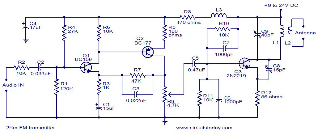
With a matching antenna, the FM transmitter circuit shown here can transmit signals up to a range of 2 kilo meters. The transistor Q1 and Q2 forms a classic high sensitive preamplifier stage. The audio signal to be transmitted is coupled to the base of Q1 through capacitor C2. R1, R3, R4, R6, R5 and R9 are the biasing resistors for the preamplifier stage comprising of Q1 and Q2. Transistor Q3 performs the collective job of oscillator, mixer and final power amplifier.C9 and L1 forms the tank circuit which is essential for creating oscillations. Inductor L2 couples the FM signal to the antenna.
Circuit diagram.
2km Fm transmitter
Notes.
  • Assemble the circuit on a good quality PCB.
  • The circuit can be powered from anything between 9 to 24V DC.
  • Inductor L3 can be a VK220J type RFC.
  • For L1 make 3 turns of 1mm enamelled copper wire on a 10mm diameter plastic former. On the same core make 2 turns of 1 mm enamelled copper wire close to L1 and that will be L2.
  • Frequency can be adjusted by varying C9.
  • R9 can be used to adjust the gain.
  • For optimum performance, value of C8 must be also adjusted.
  • Using a battery for powering the circuit will reduce noise.
-----------------------------------------------------------------------------------------------------------


Water Level Indicator

No comments:

Simple Water Level Indicator

Water Level Indicator

Description

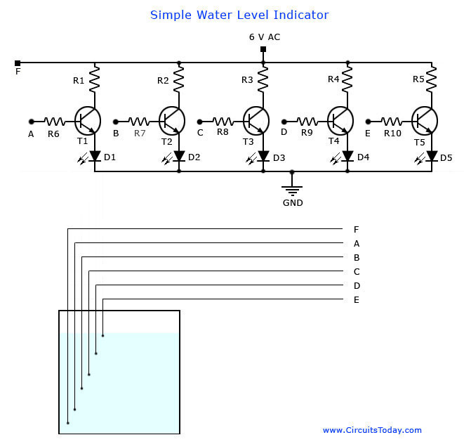
This is the circuit diagram of a simple corrosion free water level indicator for home and industries. In fact the the level of any conductive non corrosive liquids can be measured using this circuit. The circuit is based on 5 transistor switches. Each transistor is switched on to drive the corresponding LED , when its base is supplied with current through the water through the electrode probes.
One electrode probe is (F) with 6V AC is placed at the bottom of tank. Next probes are placed step by step above the bottom probe. When water is rising the base of each transistor gets electrical connection to 6V AC through water and the corresponding probe. Which in turn makes the transistors conduct to glow LED and indicate the level of water. The ends of probes are connected to corresponding points in the circuit as shown in circuit diagram.Insulated Aluminum wires with end insulation removed will do for the probe. Arrange the probes in order on a PVC pipe according to the depth and immerse it in the tank.AC voltage is use to prevent electrolysis at the probes. So this setup will last really long. I guarantee at least a 2 years of maintenance free operation. That’s what I got and is still going.

Components

T1 – T5 BC 548 or 2N2222 Transistors
R1-R5 2.2K 1/4 W Resistors
R6-R10 22K 1/4 W Resistors
D1 – D5 LED’s ( color your choice)

Notes:

Use a transformer with 6V 500 mA output for power supply. Do not use a rectifier! we need pure AC. Use good quality insulated Aluminum wire for probes. If Aluminum wires are not available try Steel or Tin.Copper is the worst. Try the circuit first on a bread board and if not working properly, make adjustments with the resistance values. This is often needed because conductivity of water changes slightly from place to place. The type number of the transistors used here are not critical and any small signal NPN transistor will do the job. Few other suitable type numbers are BC546, BC107, PN2222, BC337, BF494, ZTX300, BEL187 etc. The circuit can be enclosed in a plastic box with holes for revealing the LEDs .

Water Level Indicator Circuit Diagram and Sensor Arrangement.


Water Level Indicator Circuit
Water Level Indicator


If you need a fully automatic water level controller circuit then try this circuit  Water level controller. The circuit is fully based primarily on transistors. The sensing section is somewhat similar to this circuit but there is additional circuitry for switching the pump ON when the water level falls below a set level and the pump will be switched OFF when the tank is full. Few transistors , one 555IC and an electromagnetic relay is used for realizing the control section. The circuit is very simple cost effective , reliable and many guys have successfully assembled it.I am also working on a float type water level indicator/controller using the float type fuel gauge mechanism used in motor cycles.The level sensor section is  finished and now I am working on the control circuitry. I will add the circuit here as soon as it is finished


Note:- We have recently developed a much better and fully functional Water Level Controller circuit using 8051 Microcontroller. This water level controller monitors the level of the over head tank  and automatically switches on the water pump when ever the level goes below a preset limit. You may see the circuit and try it.

---------------------------------------------------------------------------------------------------

LCD Control using UART Serial Port

No comments:
Introduction:

When you write an LCD Program to
write your name or any text, you can only display the same text at all times. If you have to change the text, you have to change the code, recompile it again and then reprogram it. Instead of doing all this, you can just connect your circuit to serial port of computer and change the text on LCD instantly using the hyperterminal of the PC. You can just type any text in the hyperterminal and press ENTER key. The text will be displayed on the LCD instantly. You can customize the display by changing the pattern.


AVR GCC CODE
/*
Purpose:It will take input from the terminal and writes that on LCD

Hardware: 
ATmega8 @ 16MHz 
PC Software : Hyper terminal @ 19200 baud 
No Parity,1 Stop Bit, 
Flow Control = NONE 
*/ 
#include  
#include  
#include   
#include 
#include "uart.h" 
#include "lcd.h" 
 
static int uart_putchar(char c, FILE *stream);
static FILE mystdout = FDEV_SETUP_STREAM(uart_putchar, NULL, _FDEV_SETUP_WRITE);
 
static int uart_putchar(char c, FILE *stream)
{
if (c == '\n')
uart_putchar('\r', stream);
loop_until_bit_is_set(UCSRA, UDRE);
UDR = c;
return 0;
}
 
int main()
{
stdout = &mystdout;
   //Initialize the LCD Module. 
   LCDInit(LS_BLINK|LS_ULINE);
   LCDClear();
   //USART Initialisation 19200bps @ 16MHz crystal 
   USARTInit(51);
char str[20],data; int i=0; while(1) { printf("\n PLEASE ENTER THE STRING : "); for(i=0;;i++) { data = USARTReadChar();
//saving the given string
   USARTWriteChar(data);
   str[i]= data;
   if((str[i]=='\n') ||( str[i]=='\r'))
   {
   str[i]='\0';
   break;
   }
   }
LCDClear();
LCDWriteString(str);
//displaying the saved string
printf("\n Finished \n"); _delay_ms(1000); } }

Implementation:
Open the hyperterminal in your computer. Set the settings as per the code. Then reset your microcontroller. You will see "enter the string : ". Enter the text and press ENTER key. You will get "Finished". You will see the text you entered on the display.


Downloads:
Files related to this project. Click here to download

NEXT VERSION:
The text will display only when you enter the text from terminal. I am developing this code for new options. In the later version of this project, the entered text is saved in the EEPROM and if you change the code directly from the terminal.
I will be updating this post regularly, so subscribe to my blog newsletter(top right of this page) for updated information. If you have any doubts, post you comments here or mail me @ arifuddin2007@gmail.com Arifuddin Sheik

Circuit for controlling 8 appliances using TV Remote

2 comments:
IR decoder Circuit:


The IR circuit can be used to switch devices using TV Remote. Normal circuits can switch only one device. But using this circuit, different devices can be controlled using same remote with different switches. In this circuit, we interfaced 8 devices. These devices are switched using remote keypad -1 to 8. AT89S52 microcontroller is used to control the inputs and outputs. TSOP 1738 (infrared receiver) is used to receive the infrared signals from TV Remote. ULN2803 (High voltage, high current) buffer is used to drive relays.
Circuit Diagram:

IR Decode Circuit
RC-5 Protocol: To understand the operation the details of RC-5 Protocol has to be studied.
Buy an 8 channel relay board for easy installation as the board will contain relay mate connectors for connecting the switch board wires. Post your doubts if you have any...


TV Remote controlled home appliance circuit

No comments:
This is one of the popular EFY circuit. i build this one very easily. The circuit consists of very less components and simple in design.


Connect this circuit to any of your home appliances (lamp, fan, radio, etc) to make the appliance turn on/off from a TV, VCD or DVD remote control. The circuit cane activated from up to 10 metres. The 38kHz infrared (IR) rays generated by the remote control are received by IR receiver module TSOP1738 of the circuit. Pin 1 of TSOP1738 is connected to ground, pin 2 is connected to the power supply through resistor R5 and the output is taken from pin 3. The output signal is amplified by transistor T1 (BC558).
The amplified signal is fed to clock pin 14 of decade counter IC CD4017 (IC1). Pin 8 of IC1 is grounded, pin 16 is connected to Vcc and pin 3 is connected to LED1 (red), which glows to indicate that the appliance is ‘off.’ The output of IC1 is taken from its pin 2. LED2 (green) connected to pin 2 is used to indicate the ‘on’ state of the appliance. Transistor T2 (BC548) connected to pin 2 of IC1 drives relay RL1. Diode 1N4007 (D1) acts as a freewheeling diode. The appliance to be controlled is connected between the pole of the relay and neutral terminal of mains. It gets connected to live terminal of AC mains via normally opened (N/O) contact when the relay energises. you can use any NPN transistor inplace of BC548. You can also use SL100 or any NPN transistor lying around you.

The delay depends on the C1 capacitor. Using higher value capacitor will create more delay and using less value capacitor will switch the circuit more than 2 times when you press a remote. Analyse the circuit by placing the 10uf capacitor in place of C1 (100uf).

personally I faced many problems using relay for the first time. A detailed explanation regarding relays can be found here..

If you face any problems soldering this circuit, post here. This is simple than the previous version of this type of this circuit.  
 
-------------------------------------------------------------------------------------------------------