Description.
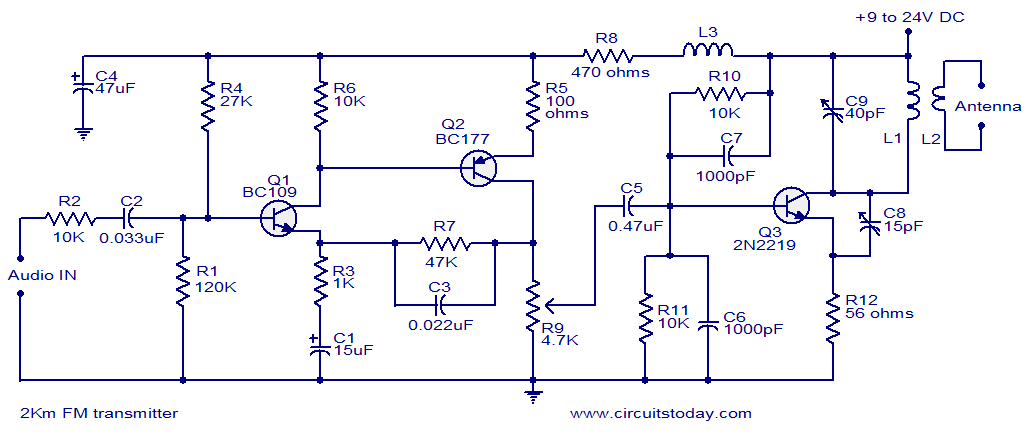
With a matching antenna, the FM transmitter circuit shown here can transmit signals up to a range of 2 kilo meters. The transistor Q1 and Q2 forms a classic high sensitive preamplifier stage. The audio signal to be transmitted is coupled to the base of Q1 through capacitor C2. R1, R3, R4, R6, R5 and R9 are the biasing resistors for the preamplifier stage comprising of Q1 and Q2. Transistor Q3 performs the collective job of oscillator, mixer and final power amplifier.C9 and L1 forms the tank circuit which is essential for creating oscillations. Inductor L2 couples the FM signal to the antenna.
With a matching antenna, the FM transmitter circuit shown here can transmit signals up to a range of 2 kilo meters. The transistor Q1 and Q2 forms a classic high sensitive preamplifier stage. The audio signal to be transmitted is coupled to the base of Q1 through capacitor C2. R1, R3, R4, R6, R5 and R9 are the biasing resistors for the preamplifier stage comprising of Q1 and Q2. Transistor Q3 performs the collective job of oscillator, mixer and final power amplifier.C9 and L1 forms the tank circuit which is essential for creating oscillations. Inductor L2 couples the FM signal to the antenna.
Circuit diagram.
- Assemble the circuit on a good quality PCB.
- The circuit can be powered from anything between 9 to 24V DC.
- Inductor L3 can be a VK220J type RFC.
- For L1 make 3 turns of 1mm enamelled copper wire on a 10mm diameter plastic former. On the same core make 2 turns of 1 mm enamelled copper wire close to L1 and that will be L2.
- Frequency can be adjusted by varying C9.
- R9 can be used to adjust the gain.
- For optimum performance, value of C8 must be also adjusted.
- Using a battery for powering the circuit will reduce noise.
Electronics Lab
Created By Muhammad Irfan
Electronics Lab
Created By Muhammad Irfan


No comments:
Post a Comment