Showing posts with label Automatic control. Show all posts

Wednesday, November 20, 2013

Circuit for controlling 8 appliances using TV Remote

2 comments:
IR decoder Circuit:


The IR circuit can be used to switch devices using TV Remote. Normal circuits can switch only one device. But using this circuit, different devices can be controlled using same remote with different switches. In this circuit, we interfaced 8 devices. These devices are switched using remote keypad -1 to 8. AT89S52 microcontroller is used to control the inputs and outputs. TSOP 1738 (infrared receiver) is used to receive the infrared signals from TV Remote. ULN2803 (High voltage, high current) buffer is used to drive relays.
Circuit Diagram:

IR Decode Circuit
RC-5 Protocol: To understand the operation the details of RC-5 Protocol has to be studied.
Buy an 8 channel relay board for easy installation as the board will contain relay mate connectors for connecting the switch board wires. Post your doubts if you have any...


TV Remote controlled home appliance circuit

No comments:
This is one of the popular EFY circuit. i build this one very easily. The circuit consists of very less components and simple in design.


Connect this circuit to any of your home appliances (lamp, fan, radio, etc) to make the appliance turn on/off from a TV, VCD or DVD remote control. The circuit cane activated from up to 10 metres. The 38kHz infrared (IR) rays generated by the remote control are received by IR receiver module TSOP1738 of the circuit. Pin 1 of TSOP1738 is connected to ground, pin 2 is connected to the power supply through resistor R5 and the output is taken from pin 3. The output signal is amplified by transistor T1 (BC558).
The amplified signal is fed to clock pin 14 of decade counter IC CD4017 (IC1). Pin 8 of IC1 is grounded, pin 16 is connected to Vcc and pin 3 is connected to LED1 (red), which glows to indicate that the appliance is ‘off.’ The output of IC1 is taken from its pin 2. LED2 (green) connected to pin 2 is used to indicate the ‘on’ state of the appliance. Transistor T2 (BC548) connected to pin 2 of IC1 drives relay RL1. Diode 1N4007 (D1) acts as a freewheeling diode. The appliance to be controlled is connected between the pole of the relay and neutral terminal of mains. It gets connected to live terminal of AC mains via normally opened (N/O) contact when the relay energises. you can use any NPN transistor inplace of BC548. You can also use SL100 or any NPN transistor lying around you.

The delay depends on the C1 capacitor. Using higher value capacitor will create more delay and using less value capacitor will switch the circuit more than 2 times when you press a remote. Analyse the circuit by placing the 10uf capacitor in place of C1 (100uf).

personally I faced many problems using relay for the first time. A detailed explanation regarding relays can be found here..

If you face any problems soldering this circuit, post here. This is simple than the previous version of this type of this circuit.  
 
-------------------------------------------------------------------------------------------------------
 

Tuesday, November 19, 2013

Low cost fire alarm circuit.

No comments:
Description.
When there is a fire breakout in the room the temperature increases. This ultra compact and low cost fire alarm senses fire breakout based on this fact.
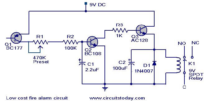
Transistor BC177 (Q1) is used as the fire sensor here. When the temperature increases the leakage current of this transistor also increases. The circuit is designed so that when there is an increase in the leakage current of Q1, transistor Q2 will get biased. As a result when there is a fire breakout the transistor Q2 will be on. The emitter of Q2 (BC 108) is connected to the base of Q3(AC 128). So when Q2 is ON Q3 will be also ON. The transistor Q3 drives the relay which is used to drive the load ie,light,bell,horn etc as an indication of the fire. The diode D1 is used as a free wheeling diode to protect it from back EMF generated when relay is switched.
Circuit diagram with Parts list.
fire-alarrm-circuit.JPG
Notes.
  • The Preset R1 can be used to desired temperature level for setting the alarm ON.
  • This is not a latching alarm,that is;when the temperature in the vicinity of the sensor decreases below the set point the alarm stops.
  • The circuit can be powered using  a 9V battery or a 9V battery eliminator.
  • All capacitors are electrolytic and must be rated at least 10V.
  • The load can be connected through the C,NC,NO points of the relay according to your need.
  • The calibration can be done using a soldering iron, and a thermo meter. Switch ON the power supply.Keep the tip of soldering iron near to the Q1. Same time also keep the thermometer close to it. When the temperature reaches your desired value adjust R1 so that relay gets ON.Done!
  • ---------------------------------------------------------------------------------------------------------------

Thursday, November 14, 2013

Sound Activated Switch

No comments:
Consider a situation in a bank or any organization where a sudden invasion by the burglars has taken place. Now all the staff has been handcuffed by the robbers and the main locker room full of valuable resources is at the mercy of the robbers. So is there any way to prevent this theft?? Yes, there is, if any buzzer is connected which can start ringing, alarming the local police or a camera fitted along with a GSM modem that can send the video to the police stations. But still the problem lies in the way to switching on these devices.
Consider another situation, when a person is at his room (in a hostel or a hotel) and a thief tries to enter the room at night when the room is dark and the owner is fast asleep. There needs to be a system for automatic switching on of the light and ringing of the buzzer alarm.
In both these situations, the solution lies in devising a way for automatic operation of a switch and to achieve this, one of the most efficient ways is a Sound Operating switch.

Two ways to design your own sound operated switch

  • Using a audio Amplifier and a timer
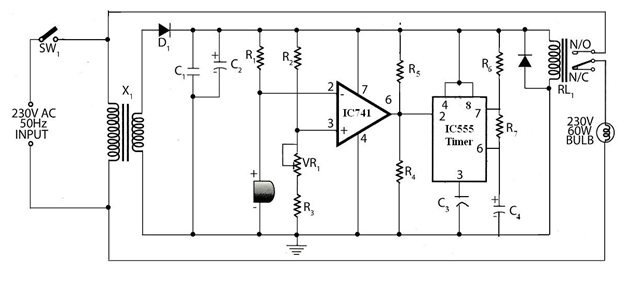
A basic sound operating switch can be constructed using an audio amplifier IC, a comparator, a 555 timer operating in monostable mode, a relay and a load. Here the basic idea is to change the output of the timer with input from the microphone, in order to switch on the load. The load can be a incandescent lamp or a LED lamp or a motor.
The audio signal is received by the microphone, which converts the audio signal to electrical signals. The signal is given to the pin2 of comparator IC 741. The other input pin 3 of the comparator is given by the reference voltage set by the potentiometer arrangement.
Simple Sound Operated Switch circuit
In absence of any audio signal, pin 2 is at logic high and the output of comparator is at logic low, giving a low signal to the trigger pin of the 555 timer. The output of the timer is thus at logic high, keeping the relay at off condition. When a sound is heard the microphone detects it and converts it to electrical signal and the signal is applied to pin2 of the comparator and since this pin is now at logic low, the comparator output is at logic high, triggering a logic high signal to the trigger pin of the timer. The timer output is thus at logic low, driving on the relay, which in turn switches on the load( A bulb) for a time determined by the RC combination.
  • A Sound Operated Switch using Counter IC
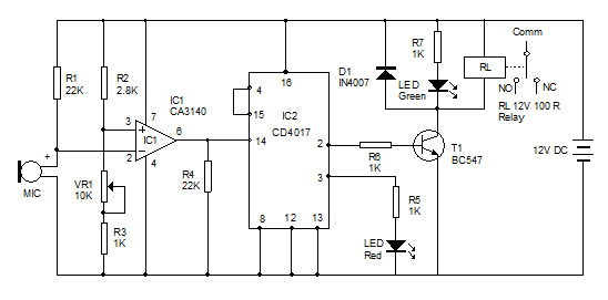
You can use this circuit to operate a Relay through the sound of claps. It is highly sensitive and can detect the sound of the clap from a distance of 1-2 meters. AC loads such as lamps, fans etc can be connected through the relay. This circuit has three sections. A sensitive MIC amplifier, A Toggle switch based on IC CD4017 and a Relay driver. IC CD4017 is a decade counter where the output count number is shown by the corresponding output number pin going high.
Condenser Microphone picks up the sound vibrations and generates minute voltage across its terminals. These feeble signals are amplified by IC1. Resistor R1, R3 and variable resistor VR1 adjust the sensitivity of the amplifier. Resistor R1 set the sensitivity of Mic. The amplified output pulses from IC1 passes to the input of IC2 (CD 4017). Resistor R4 keeps the input (pin14) of IC2 low so as to prevent false triggering. IC2 is a decade counter IC which is wired as a toggle switch. That its outputs 1 and 2 (pins 2 and 3) becomes high and low alternately when the input pin14 receives pulses from IC1.  Pin4 (output4) is connected to the reset pin15 so that further counting will be inhibited. The high output from IC2 passes through the current limiter R6 to the base of switching transistor T1. When T1 conducts, Green LED and the Relay turns on. In the next clap, output pin 2 becomes low to switch off the relay and the Green LED. Red LED indicates the OFF position of the load.
In other words, when we first make a clapping sound, the audio signal gets converted by the microphone to electrical signal and amplified by the operational amplifier, which gives the output pulse. When the counter receives the first pulse the pin 2 goes high and the relay driver is switched on to energize the relay and thus switch on the LED. When we again make a clapping sound, the amplifier IC generates another pulse. This time the pin 2 goes low and pin 3 goes high, causing the red LED to glow. The relay is now switched off and the LED is in off condition.
Sound-Sensitive-Switch-Circ
Note: It is better to connect the Microphone directly on the PCB using two pieces of the trimmed leads of resistor or capacitor. If Microphone is connected with wires, sensitivity may be reduced. Enclosing the Microphone in a tube will increase the sensitivity considerably. Adjust VR1 to get maximum sensitivity and range.

4 Sound Operated switches available in the market

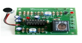
Sound Operated Electronic Switch
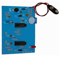
It is a sound operated electronic switch kit by Electro Kits. It operates on a 9V battery and uses a electrets microphone. It switches on and off an LED mounted on the kit.
  • Automatic Voice Activated Switch
Automatic Voice Activated Switch
Its switching time is up to 60seconds and supports loads upto 3A-115V or 5A-12V
Clap On Off Switch
It is a microprocessor controlled switch operating on 1 or 2 claps. It has a relay power rating of 24VDC/AC 3A. It works on a power supply of 12V dc.
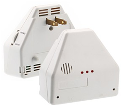
1382313 Model number Sound Operated Switch
It is a 1382313 model number sound operated switch operating on a power of 250W max with a supply voltage of 120V. It works in two modes. In Home mode, it can operate one or two appliances. In the Away mode, it will operate on any noise to switch on the connected appliance.


Wednesday, November 13, 2013

Automatic Darkness-Controlled Lighting System

No comments:
Make tubelights automatically switch on at night and switch off in daytime using this automatic control system. Automatic darkness-controlled lighting system means that whenever there is darkness, light source like bulb or tubelight glows automaticly.

Fig. 1: Circuit of automatic darkness-controlled lighting system
The circuit works off regulated 5V and uses triac BT136, NOT gate 7404 and light-dependent resistor (LDR).

Operation of the circuit is simple. During daytime, low resistance of LDR1 makes pin 1 of gate N1 low and its output pin 2 goes high. This high output is applied to input pin 3 of gate N2. As a result, the output of gate N2 goes low. Hence no gate signal is applied to triac BT136 (triac 1) and it acts as an open circuit and the bulb does not glow.

Fig. 2: Pin configuration andsymbol of triac BT136
At night, the high resistance of LDR1 makes pin 1 of gate N1 high and its output pin 2 goes low. This low output is applied to input pin 3 of gate N2. As a result, the output of gate N2 goes high, which is applied to the gate of triac BT136 (triac 1) and it acts as a short circuit and the bulb start glowing.

Assemble the circuit on a general-purpose PCB and keep at a suitable place. Keep LDR1 at such a place that enough light falls on it in day-time. You can also use this circuit as a street light controller.

Simple Electronic Lock Project

No comments:


There are six (or more) push switches. To 'unlock' you must press all the correct ones at the same time, but not press any of the cancel switches. Pressing just one cancel switch will prevent the circuit unlocking. When the circuit unlocks it actually just turns on an LED for about one second, but it is intended to be adapted to turn on a relay which could be used to switch on another circuit.
Please Note: This circuit just turns on an LED for about one second when the correct switches are pressed. It does not actually lock or unlock anything!
This project uses a 555 monostable circuit.

Parts Required


  • resistors: 470, 100k ×2, 1M
  • capacitors: 0.1µF, 1µF 16V radial
  • red LED
  • 555 timer IC
  • 8-pin DIL socket for IC
  • on/off switch
  • push-switch ×6 (or more)
  • battery clip for 9V PP3
  • stripboard 12 rows × 25 holes


Stripboard Layout

Stripboard layout for simple electronic lock

Circuit diagram

Circuit diagram for simple electronic lock


Monday, November 11, 2013

How to use a relay

No comments:
A relay is an electrically operated switch. Current flowing through the coil of the relay creates a magnetic field which attracts a lever and changes the switch contacts. The coil current can be on or off so relays have two switch positions and they are double throw (changeover) switches.
The relay’s switch connections are usually labeled COM(POLE), NC and NO:
COM/POLE= Common, NC and NO always connect to this, it is the moving part of the switch.
NC = Normally Closed, COM/POLE is connected to this when the relay coil is not magnetized.
NO = Normally Open, COM/POLE is connected to this when the relay coil is MAGNETIZED and vice versa.
A relay shown in the picture is an electromagnetic or mechanical relay.
  
Fig. Relay and its symbol
There are 5 Pins in a relay. Two pins A and B are two ends of a coil that are kept inside the relay. The coil is wound on a small rod that gets magnetized whenever current passes through it.
COM/POLE is always connected to NC(Normally connected) pin. As current is passed through the coil A, B, the pole gets connected to NO(Normally Open) pin of the relay.
Here is an example,
First of all try the following circuit.
This is a dark sensor circuit.
Output of this circuit: When you block light falling on LDR, the circuit switches on the LED- D1.
Now, replace LED-D1 and R2- 330R with a relay and diode.
Reconfigure the circuit as shown in the figure below:
Note: In R3, you can keep any resistor from 330R to 4.7K, this resistor is for sensitivity of the dark sensor.
The following circuit also works as a dark sensor. When you block light falling on LDR, the relay gets activated and Pole of relay gets connected to NO pin that eventually gives power to LED- D1.
 
Fig. Dark sensor using two transistors and a relay.

Light sensor using relay and transistors

In this case, the configuration of relay has been changed. Here, NO (Normally open) terminal has been left open. In normal case, the D1-LED remains ON. When light falling on LDR is interrupted, pole of relay gets connected to NO terminal. Hence, NC (Normally connected) terminal does not get power and that switches the D1- LED off.
Fig. Light sensor using two transistors and a relay.
Connect to COM(pole) and NO if you want the switched circuit to be on when the relay coil is on.
Connect to COM(pole) and NC if you want the switched circuit to be on when the relay coil is off.

WORKING WITH 220V

WARNING: IF YOU ARE A NOVICE DO NOT PLAY WITH 220V AC. CALL AN EXPERIENCED PERSON FOR ASSISTANCE.
Fig. Dark sensor circuit for 220V powered lights.
A relay can be used to turn on lights working on 220V, AC. The AC powered light has to be connected to relay as shown in the picture above.
Fig. Connecting wires on relay
The following video shows a soldered/finished prototype.

PROTECTION DIODE FOR RELAY

Fig. Protection diode in the circuit
Transistors and ICs must be protected from the brief high voltage produced when a relay coil is switched off. The diagram shows how a signal diode (eg 1N4148or 1N4001) is connected ‘backwards’ across the relay coil to provide this protection.
Current flowing through a relay coil creates a magnetic field which collapses suddenly when the current is switched off. The sudden collapse of the magnetic field induces a brief high voltage across the relay coil which is very likely to damage transistors and ICs. The protection diode allows the induced voltage to drive a brief current through the coil (and diode) so the magnetic field dies away quickly rather than instantly. This prevents the induced voltage becoming high enough to cause damage to transistors and ICs.

GENERAL SPECIFICATION OF A RELAY

06VDC- means that the voltage across the relay coil has to be 6V-DC.
50/60Hz- The relay can work under 50/60Hz AC.
7A, 240VAC- The maximum AC current and AC voltage specification that can be passed through NC, NO and pole pins/terminals of relay.