Showing posts with label Audio. Show all posts

Monday, November 18, 2013

100 Watt sub woofer amplifier.

2 comments:
Description.
This is the circuit diagram of a fully transistorized sub woofer amplifier that can produce an output of 100W.There are seven transistors including four in the output stage. The transistors Q1 and Q2 form the preamplifier stage. Transistors Q4 to Q7 form the output stage. Since no ICs are used the circuit is very robust and can be easily assembled on a general purpose PCB.
Circuit diagram with Parts list.
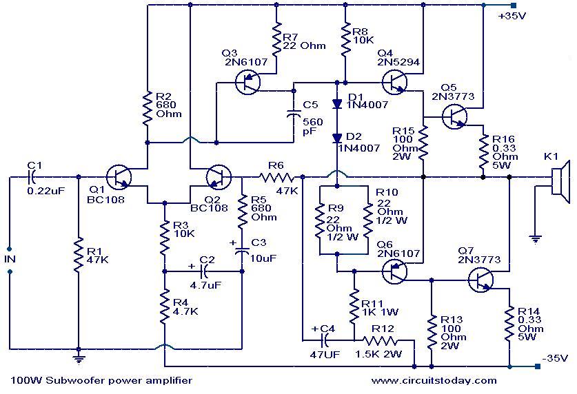
100-w-subwoofer-amplifier-circuit
Notes.
  • The circuit can be powered from a +35V/-35V, 5A dual power supply.
  • Use a 100W, 12 inch sub woofer at the output.
  • All electrolytic capacitors must be rated 100V.
  • The transistor Q4 to Q7 must be fitted with heat sinks.

-----------------------------------------------------------------------------------------------------

Sunday, November 17, 2013

Very Simple Bench Amplifier

2 comments:
A small 325mW amplifier with a voltage gain of 200 that can be used as a bench amplifier, signal tracer or used to amplify the output from personal radios, etc. The circuit is based on the National Semiconductor LM386 amplifier. In the diagram above, the LM386 forms a complete non-inverting amplifier with voltage gain of x200. A datasheet in PDF format can be downloaded from the National Semiconductor website. The IC is available in an 8 pin DIL package and several versions are available; the LM386N-1 which has 325mW output into an 8 ohm load, the Lm386N-3 which has 700mW output and the LM386N-4 which offers 1000mW output. all versions work in this circuit. The gain of the Lm386 can be controlled by the capacitor across pins 1 and 8. With the 10u cap shown above, voltage gain is 200, omitting this capacitor and the gain of the amplifier is 20.

Finished project:
Circuit diagram:

Bench Amplifier Circuit Diagram

The IC works from 4 to 12Volts DC, 12Volt being the maximum recommended value. The internal input impedance of the amplifier is 50K, this is shunted with a 22k log potentiometer so input impedance in this circuit will be lower at about 15k. The input is DC coupled so care must be taken not to amplify any DC from the preceeding circuit, otherwise the loudspeaker may be damaged. A coupling capacitor may included in series with the 22k control to prevent this from happening.

Read more:

Friday, November 15, 2013

Microphone Amplifier

No comments:
 
This amplifies sound from a microphone.
  • The output is up to 1 volt and a gain of -100
  • The output can be adjusted from 0 - 100%
Supply Voltage (+V): 5 to 20 volts.


NOTES
  • This circuit uses an operational-amplifier IC
  • It is an "inverting" amplifier which means a positive input will give a negative output, and vice-verca. This will not matter in most cases.


PCB size: 51mm x 25mm


Thursday, October 10, 2013

Portable Audio Amplifier

1 comment:


Description


Stereo per channel
VCC=9V;RL=4?/3W
VCC=9V;RL=8?/2W

Bridge Application
VCC=9V;RL=8?/5W
VCC=9V;RL=4?/8W

Supply Voltage min = DC3v @ 500mA
Supply Voltage max = DC12v @ 500mA
Supply Voltage recommended = DC9v @500mA

DESCRIPTION
Above circuits are based on TEA2025 is a monolithic integrated audio amplifier in a 16-pin plastic dual in line package manufactured by UTC .Circuit has an Internal Thermal Protector. It is designed for portable cassette players and radios. You can also use it as your PC Audio Amplifier. A few external components required to build this circuit. Use 9v transformer to play the circuit. But not more than DC12v. Because it can damage the amplifier IC. So build n Enjoy.


  Electronics Lab ,Created By Muhammad Irfan  Electronics Lab ,Created By Muhammad Irfan  Electronics Lab ,Created By Muhammad Irfan  Electronics Lab ,Created By Muhammad Irfan

200W Audio Amplifier

No comments:


Description


Output Power : 200Watts
Load Resistance : 8ohms
Input impedance : 55K
Maximum supply voltage : (+95v)-0-(-95v)
Recommended supply voltage : (+66v)-0-(-66v)

This complete high quality, low noise mono audio power amplifier is based around the Hybrid Integrated Circuit STK4050 manufactured by Sanyo. The circuit incorporates volume and has a maximum music output power of 200W.The circuit incorporates an on board power supply; therefore, only centre tapped transformer is required to power the circuit. I t has very good quality sound. U can use it with your Home Theatre your PC & etc... You can also use it as Subwoofer Amplifier. It is a compact package for THIN-TYPE Audio sets. Easy Heatsink design to disperse heat generated in THIN-TYPE audio sets. Constant-Current circuit to Reduce supply switch-ON and switch-OFF shock noise. External supply switch-On and switch-OFF shock noise muting, Load short-circuit protection, thermal shutdown and other circuits can be tailored-designed.


  Electronics Lab ,Created By Muhammad Irfan  Electronics Lab ,Created By Muhammad Irfan  Electronics Lab ,Created By Muhammad Irfan  Electronics Lab ,Created By Muhammad Irfan

20W Bridge Audio Amplifier

No comments:


Specifications


20W Bridge Audio Amplifier kit, based on the TDA2005 IC, a class B dual audio amplifier, specifically designed for car radio applications etc.
  • Power supply - 18 VDC
  • Output power - 20 W, 4 Ω
  • IC built in Thermal Shut-down, Load dump voltage surge protected
  • Terminal pins for connecting left and right audio signal inputs
  • Relimate Connector for connecting Potentiometer (POT) for volume adjustment
  • Power Battery Terminal (PBT) for easy power supply and speaker connection
  • Power-On LED indicator
  • Heatsink for IC
  • Four mounting holes of 3.2 mm each with nut and stud
  • PCB dimensions 63 mm x 65 mm

    Schematic


    Parts List


    PCB


      Electronics Lab ,Created By Muhammad Irfan  Electronics Lab ,Created By Muhammad Irfan  Electronics Lab ,Created By Muhammad Irfan  Electronics Lab ,Created By Muhammad Irfan


Tiny audio amplifier using LM386

No comments:
Specifications


The Tiny Audio Amplifier kit is a good choice for battery operation.  It is based on LM386 IC.
  • Power supply - 6 - 12 VDC
  • Output power - 1 W, 8 Ohm
  • The quiescent power drain is only 24 mW when operating from 6 VDC
  • Self-centering output quiescent voltage
  • Onboard PRESET to adjust volume
  • Terminal pins for connecting power supply, audio signal and speaker
  • Power-On LED indicator
  • ON/OFF PCB mounted slide switch for power supply
  • Four mounting holes of 3.2 mm each
  • PCB dimensions 44 mm x 44 mm


    Schematic


  Parts List
 _________________________________________________________________________________________


Inputs - Outputs configuration


PCB


  Electronics Lab ,Created By Muhammad Irfan  Electronics Lab ,Created By Muhammad Irfan  Electronics Lab ,Created By Muhammad Irfan  Electronics Lab ,Created By Muhammad Irfan

2N3055 Power Amplifier

No comments:
Simple and low cost. The optimal supply voltage is around 50V, but this amp work from 30 to 60V. The maximal input voltage is around 0.8 - 1V. As you can see, in this design the components have a big tolerance, so you can build it almost of the components, which you find at home. The and transistors can be any NPN type power transistor, but do not use Darlington types... The output power is around 60W.

Some comments: - capacitor C1 regulates the low frequencies (bass), as the capacitance grows, the low frequncies are getting louder.
- capacitor C2 regulates the higher frequencies (treble), as the capacitance grows, the higher frequencies are getting quiter.
- this is a class B amplifier, this means, that a current must flow through the end transistors, even if there is no signal on the input. This current can be regulated with the 500Ω trimmer resistor. As this current incrases, the sound of the amplifier gets better, but the end transistors are more heating. But if this current decrases, the transistors are not heating so much, but the sound gets worse...


  Electronics Lab ,Created By Muhammad Irfan  Electronics Lab ,Created By Muhammad Irfan  Electronics Lab ,Created By Muhammad Irfan  Electronics Lab ,Created By Muhammad Irfan  Electronics Lab ,Created By Muhammad Irfan