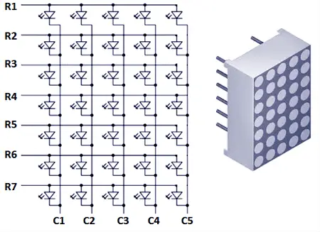
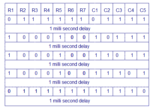
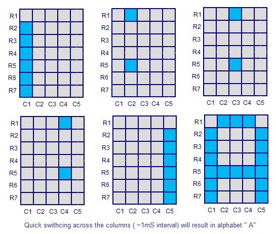
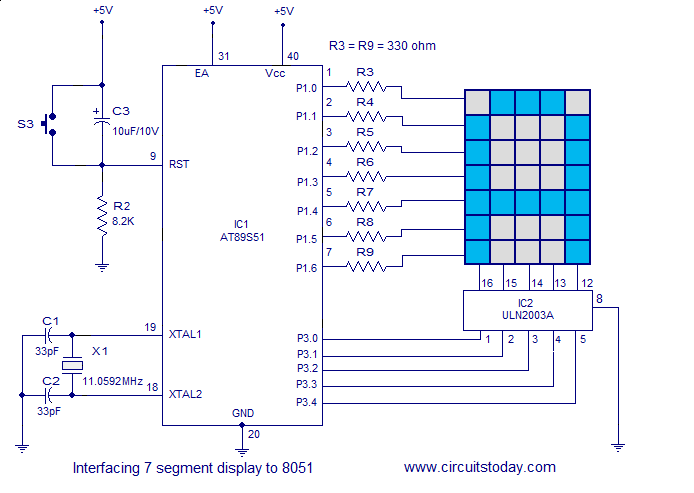
Working of Relays
In this article, the basics of a relay like energized relay and de-energized relay are explained in detail. Also, the design, construction, working, applications, and also relay selection is explained in detail.
What is a relay?
We know that most of the high end industrial application devices have relays for their effective working. Relays are simple switches which are operated both electrically and mechanically. Relays consist of a n electromagnet and also a set of contacts. The switching mechanism is carried out with the help of the electromagnet. There are also other operating principles for its working. But they differ according to their applications. Most of the devices have the application of relays.
Why is a relay used?
The main operation of a relay comes in places where only a low-power signal can be used to control a circuit. It is also used in places where only one signal can be used to control a lot of circuits. The application of relays started during the invention of telephones. They played an important role in switching calls in telephone exchanges. They were also used in long distance telegraphy. They were used to switch the signal coming from one source to another destination. After the invention of computers they were also used to perform Boolean and other logical operations. The high end applications of relays require high power to be driven by electric motors and so on. Such relays are called contactors.
Relay Design
There are only four main parts in a relay. They are
- Electromagnet
- Movable Armature
- Switch point contacts
- Spring
The figures given below show the actual design of a simple relay.

- Relay Construction
It is an electro-magnetic relay with a wire coil, surrounded by an iron core. A path of very low reluctance for the magnetic flux is provided for the movable armature and also the switch point contacts. The movable armature is connected to the yoke which is mechanically connected to the switch point contacts. These parts are safely held with the help of a spring. The spring is used so as to produce an air gap in the circuit when the relay becomes de-energized.
How relay works?
The working of a relay can be better understood by explaining the following diagram given below.

- Relay Design
The diagram shows an inner section diagram of a relay. An iron core is surrounded by a control coil. As shown, the power source is given to the electromagnet through a control switch and through contacts to the load. When current starts flowing through the control coil, the electromagnet starts energizing and thus intensifies the magnetic field. Thus the upper contact arm starts to be attracted to the lower fixed arm and thus closes the contacts causing a short circuit for the power to the load. On the other hand, if the relay was already de-energized when the contacts were closed, then the contact move oppositely and make an open circuit.
As soon as the coil current is off, the movable armature will be returned by a force back to its initial position. This force will be almost equal to half the strength of the magnetic force. This force is mainly provided by two factors. They are the spring and also gravity.
Relays are mainly made for two basic operations. One is low voltage application and the other is high voltage. For low voltage applications, more preference will be given to reduce the noise of the whole circuit. For high voltage applications, they are mainly designed to reduce a phenomenon called arcing.
Relay Basics
The basics for all the relays are the same. Take a look at a 4 – pin relay shown below. There are two colours shown. The green colour represents the control circuit and the red colour represents the load circuit. A small control coil is connected onto the control circuit. A switch is connected to the load. This switch is controlled by the coil in the control circuit. Now let us take the different steps that occour in a relay.

- relay operation
As shown in the circuit, the current flowing through the coils represented by pins 1 and 3 causes a magnetic field to be aroused. This magnetic field causes the closing of the pins 2 and 4. Thus the switch plays an important role in the relay working. As it is a part of the load circuit, it is used to control an electrical circuit that is connected to it. Thus, when the relay in energized the current flow will be through the pins 2 and 4.
")
- Energized Relay (ON)
- De – Energized Relay (OFF)
As soon as the current flow stops through pins 1 and 3, the switch opens and thus the open circuit prevents the current flow through pins 2 and 4. Thus the relay becomes de-energized and thus in off position.
")
- De-Energized Relay (OFF)
In simple, when a voltage is applied to pin 1, the electromagnet activates, causing a magnetic field to be developed, which goes on to close the pins 2 and 4 causing a closed circuit. When there is no voltage on pin 1, there will be no electromagnetic force and thus no magnetic field. Thus the switches remain open.
Pole and Throw
Relays have the exact working of a switch. So, the same concept is also applied. A relay is said to switch one or more poles. Each pole has contacts that can be thrown in mainly three ways. They are
- Normally Open Contact (NO) – NO contact is also called a make contact. It closes the circuit when the relay is activated. It disconnects the circuit when the relay is inactive.
- Normally Closed Contact (NC) – NC contact is also known as break contact. This is opposite to the NO contact. When the relay is activated, the circuit disconnects. When the relay is deactivated, the circuit connects.
- Change-over (CO) / Double-throw (DT) Contacts – This type of contacts are used to control two types of circuits. They are used to control a NO contact and also a NC contact with a common terminal. According to their type they are called by the names break before make and make before breakcontacts.
Relays are also named with designations like
- Single Pole Single Throw (SPST) – This type of relay has a total of four terminals. Out of these two terminals can be connected or disconnected. The other two terminals are needed for the coil.
- Single Pole Double Throw (SPDT) – This type of a relay has a total of five terminals. Out f these two are the coil terminals. A common terminal is also included which connects to either of two others.
- Double Pole Single Throw (DPST) – This relay has a total of six terminals. These terminals are further divided into two pairs. Thus they can act as two SPST’s which are actuated by a single coil. Out of the six terminals two of them are coil terminals.
- Double Pole Double Throw (DPDT) – This is the biggest of all. It has mainly eight relay terminals. Out of these two rows are designed to be change over terminals. They are designed to act as two SPDT relays which are actuated by a single coil.
Relay Applications
- Relays are used to realize logic functions. They play a very important role in providing safety critical logic.
- Relays are used to provide time delay functions. They are used to time the delay open and delay close of contacts.
- Relays are used to control high voltage circuits with the help of low voltage signals. Similarly they are used to control high current circuits with the help of low current signals.
- They are also used as protective relays. By this function all the faults during transmission and reception can be detected and isolated.
Relay Selection
You must note some factors while selecting a particular relay. They are
- Protection – Different protections like contact protection and coil protection must be noted. Contact protection helps in reducing arcing in circuits using inductors. Coil protection helps in reducing surge voltage produced during switching.
- Look for a standard relay with all regulatory approvals.
- Switching time – Ask for high speed switching relays if you want one.
- Ratings – There are current as well as voltage ratings. The current ratings vary from a few amperes to about 3000 amperes. In case of voltage ratings, they vary from 300 Volt AC to 600 Volt AC. There are also high voltage relays of about 15,000 Volts.
- Type of contact used – Whether it is a NC or NO or closed contact.
- Select Make before Break or Break before Make contacts wisely.
- Isolation between coil circuit and contacts
----------------------------------------------------------------------------------