A
water level controller based using 8051 is shown in this article. A lot
of water level controller projects have been published in this website
but the is the first one based on a microcontroller. This water level
controller monitors the level of the over head tank and automatically
switches on the water pump when ever the level goes below a preset
limit. The level of the over head tank is indicated using 5 leds and the
pump is switched of when the over head tank is filled.
The pump is not allowed to start if the water level
in the sump tank is low and also the pump is switched off when the level
inside the sump tank goes low during a pumping cycle. The circuit
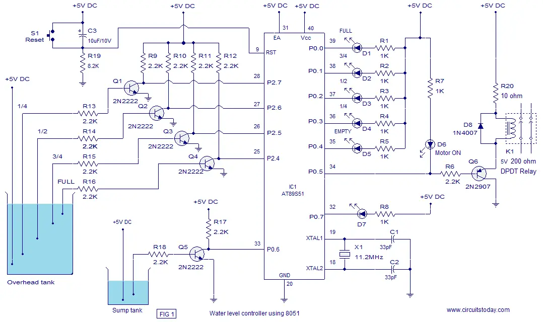
diagram of the water level controller is shown below.
The level sensor probes for the overhead tank are interfaced to the port
2 of the microcontroller through transistors. Have a look at the sensor
probe arrangement for the overhead tank in Fig1. A positive voltage
supply probe goes to the down bottom of the tank. The probes for sensing
1/4, 1/2, 3/4 and FULL levels are placed with equal spacing one by one
above the bottom positive probe. Consider the topmost (full level)
probe, its other end is connected to the base of transistor Q4 through
resistor R16. Whenever water rises to the full level current flows into
the base of transistor Q4 which makes it ON and so its collector voltage
goes low. The collector of Q4 is connected to P2.4 and a low voltage at
P2.4 means the over head tank is not FULL. When water level goes below
the full level probe, the base of Q2 becomes open making it OFF. Now
its collector voltage goes high and high at P2.4 means the tank is not
full. The same applies to other sensor probes (3/4, 1/2, 1/4) and the
microprocessor understands the current level by scanning the port pins
P2.4 ,P2.5, P2.6 and P2.7. All these port pin are high (all sensor
probes are open) means the tank is empty.
Port pin P0.5 is used to control the pump. When ever it is required
start pumping, the controller makes P0.5 low which makes transistor Q6
ON which in turn activates the relay K1 that switches the pump. Also the
LED d6 glows indicating the motor is ON. LED D7 is the low sump
indicator. When the water level in the sump tank goes low, the
controller makes P0.7 low which makes LED D7 to glow. The circuit
diagram of the water level controller is shown in the figure below.
Circuit diagram.
Program.
MOV P2,#11111111B // initiates P2 as sensor input
MOV P0,#11111111B // initiates P2 as the output port
MOV A,#00000000B
MAIN:ACALL SMPCK // checks the level of the sump tank
MOV A,P2 // moves the current status of P2 tp A
CJNE A,#11110000B,LABEL1 // checks whether tank is full
SETB P0.1
SETB P0.2
SETB P0.3
SETB P0.4
CLR P0.0 // glows full level LED
SETB P0.5
LABEL1:MOV A,P2
CJNE A,#11111000B,LABEL2 // checks whether tank is 3/4
SETB P0.0
SETB P0.2
SETB P0.3
SETB P0.4
CLR P0.1 // glows 3/4 level LED
LABEL2:MOV A,P2
CJNE A,#11111100B,LABEL3 // checks whether tank is 1/2
SETB P0.0
SETB P0.1
SETB P0.3
SETB P0.4
CLR P0.2 // glows 1/2 level LED
LABEL3:MOV A,P2
CJNE A,#11111110B,LABEL4 // checks whether tank is 1/4
SETB P0.0
SETB P0.1
SETB P0.2
SETB P0.4
CLR P0.3 // glows 1/4 level LED
JB P0.6,LABEL4
CLR P0.5 // switches motor ON
LABEL4:MOV A,P2
CJNE A,#11111111B,MAIN // checks whether tank is empty
SETB P0.0
SETB P0.1
SETB P0.2
SETB P0.3
CLR P0.4 // glows EMPTY LED
JB P0.6,MAIN // checks whether sump is low
CLR P0.5 // switches motor ON
SJMP MAIN
SMPCK:JB P0.6,LABEL5 // checks whether sump is low
SETB P0.7 // extinguishes the sump low indicator LED
SJMP LABEL6
LABEL5:SETB P0.5 // switches the pump OFF
CLR P0.7 // glows sump low indicator LED
LABEL6:RET
END


No comments:
Post a Comment