Showing posts with label Inverter. Show all posts

Tuesday, January 7, 2014

555 timer IC Inverter 12V to 220V

1 comment:
This article explains What is inverter? And how can you construct your own simple low cost 12V to 220V inverter circuit. An inverter is nothing but a DC to AC converter. Inverters are very useful electronics products for compensating emergency power failure, as it performs DC to AC conversion.
CBZ4DUQZD2JF
AC can’t be stored for future use but DC can be stored for future use in a battery. The stored DC can be converted back to AC by using power inverters.
Here is the simple inverter circuit diagram using 555 timer IC. The astable multivibrator mode operation of 555 timer utilized here for AC oscillations and these oscillations are switched via transistor 2SC4029 to a transformer. The transformer step ups the voltage to 220V AC. Use a 12V battery and Battery charger circuit for this project. Design of inverter circuit is also given. 

Circuit diagram of DC to AC inverter


Components required

  1. Power supply (12V)
  2. Resistors (3kΩ x 2; 1kΩ, 2W x 1)
  3. Capacitor (10µF)
  4. 555 timer IC
  5. Diode(1N4007)
  6. Transistor (2SC4029)
  7. 9V to 220V Step up transformer

Working of DC to AC inverter

  • This is a simple inverter circuit based on 555 timer IC. Here timer IC wired as an astable multivibrator mode.
  • The diode 1N4007 is used to get 50% duty cycle for the pulses from 555, it also reduces the design complexity.
  • The output pulse from the 555 astable multivibrator is fed to the base of power transistor 2N5192. The 2N5192 transistor works as a switch, so the 12V DC supply passed through the transformer at a rate of 50 times per second.
  • Transformer step up the 12V to 220V, thus we got 50Hz, 220VAC supply at the output of transformer secondary.

Design of Inverter circuit

555 timer Astable designed about to oscillate at 50Hz, line frequency.
Frequency of astable multivibrator is given by,
Choose C=10µF, then
Use R1=R=3kΩ 

El


******Related Topic ******


Simple Inverter

No comments:
Have you ever wanted to run a TV, stereo or other appliance while on the road or camping? Well, this inverter should solve that problem. It takes 12 VDC and steps it up to 120 VAC. The wattage depends on which tansistors you use for Q1 and Q2, as well as how "big" a transformer you use for T1. The inverter can be constructed to supply anywhere from 1 to 1000 (1 KW) watts. 
C1, C2    2              68 uf, 25 V Tantalum Capacitor  
R1, R2    2              10 Ohm, 5 Watt Resistor              
R3, R4    2              180 Ohm, 1 Watt Resistor            
D1, D2   2              HEP 154 Silicon Diode    
Q1, Q2  2              2N3055 NPN Transistor (see "Notes")    
T1           1              24V, Center Tapped Transformer (see "Notes")               
MISC     1              Wire, Case, Receptical (For Output)         


  1. Q1 and Q2, as well as T1, determine how much wattage the inverter can supply. With Q1,Q2=2N3055 and T1= 15 A, the inverter can supply about 300 watts. Larger transformers and more powerful transistors can be substituted for T1, Q1 and Q2 for more power.
  2. The easiest and least expensive way to get a large T1 is to re-wind an old microwave transformer. These transformers are rated at about 1KW and are perfect. Go to a local TV repair shop and dig through the dumpster until you get the largest microwave you can find. The bigger the microwave the bigger transformer. Remove the transformer, being careful not to touch the large high voltage capacitor that might still be charged. If you want, you can test the transformer, but they are usually still good. Now, remove the old 2000 V secondary, being careful not to damage the primary. Leave the primary in tact. Now, wind on 12 turns of wire, twist a loop (center tap), and wind on 12 more turns. The guage of the wire will depend on how much current you plan to have the transformer supply. Enamel covered magnet wire works great for this. Now secure the windings with tape. Thats all there is to it. Remember to use high current transistors for Q1 and Q2. The 2N3055's in the parts list can only handle 15 amps each.
  3. Remember, when operating at high wattages, this circuit draws huge amounts of current. Don't let your battery go dead :-).
  4. Since this project produces 120 VAC, you must include a fuse and build the project in a case.
  5. You must use tantalum capacitors for C1 and C2. Regular electrolytics will overheat and explode. And yes, 68uF is the correct value. There are no substitutions.
  6. This circuit can be tricky to get going. Differences in transformers, transistors, parts substitutions or anything else not on this page may cause it to not function.
  7. If you want to make 220/240 VAC instead of 120 VAC, you need a transformer with a 220/240 primary (used as the secondary in this circuit as the transformer is backwards) instead of the 120V unit specified here. The rest of the circuit stays the same. But it takes twice the current at 12V to produce 240V as it does 120V. 
  8. Electronics Lab Created By Muhammad Irfan


Saturday, November 30, 2013

3V to 9V DC Converters

1 comment:
Here are some 3V to 9V DC converter circuits that were requested by some of our visitors. It may be helpful to have one of this converters when no 9V battery is available or if you consider that they are too expensive. The first circuit is very simple, it uses the TL496 power supply controller, a coil and a electrolytic capacitor.


TL496 3 to 9 volt converter circuit
tl496 3 to 9V dc converter
The maximum output voltage is actually 8.6V and current is around 80mA.
The input current (the current drawn from the batteries) is 405mA at the maximum output current. Without load the current consumption is 125µA and the batteries life is around 166 days.


Here is another 1.5… 4.5V to 9V converter


3 volt to 9 volt with LMC555
This dc converter is built with the CMOS version of 555 timer. You can get 12V too if you change the zener diode to a 12V version.
3volt 9volt 555 timer
Probably there are more 3 to 9 volt dc converters but for the moment those are the only ones presented in this article.


******Related Topic ******


-------------------------------------------------------------------------------------------------------------------

1.5V Battery to 5V Voltage Converter

4 comments:

 1.5V Battery to 5V Voltage Converter


Wanna recharge your portable music player through its USB power interface, during a winter trip? Or like to energise a microcontroller based circuit using a single penlight cell? Here is an interesting circuit to generate stable and secure 5V DC (at 200mA max) from an ordinary 1.5V AA sized cell. At the heart of this circuit is IC1 MAX756 from Maxim, which is a CMOS step-up DC-DC switching regulator for small, low input voltage or battery-powered systems.


MAX756 accepts a positive input voltage down to 0.7V and converts it to a higher pin selectable output voltage of 5V (or 3.3V). Typical full-load efficiency for the this IC is greater than 87%. Max756 combine a switch-mode regulator with an N-channel MOSFET, precision voltage reference, and power-fail detector in a single monolithic device. The MOSFET is a “sense-FET” type for best efficiency, and has a very low gate threshold voltage to ensure start-up under low-battery voltage conditions (1.1V typ).
assembled circuit
inductor coilThe circuit can be easily wired on a very small rectangular common PCB.All connections should be kept as short as possible. If available,try to add a good quality 8 pin DIP socket for IC1. Note that the power inductor’s (L1) DC resistance significantly affects efficiency. For highest efficiency, limit L1’s DC resistance to 0.03 Ohm or less. A thru-hole type standard power inductor can be used. Similarly, the ESR of all capacitors (bypass and filter) affects circuit efficiency. Best performance is obtained by using specialized low-ESR capacitors.
5 Volt From 1.5 Volt Circuit Schematic


portable 1.5 V to 5 V converter schematic


Monday, November 18, 2013

Simple UPS

No comments:
Description.
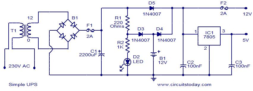
This is the circuit diagram of a simple UPS that can deliver 12V unregulated and 5V regulated DC. The transformer T1 steps down the mains voltage to 12V AC and then the bridge B1 rectifies it. The rectified signal is smoothed by the capacitor C1.When the mains supply is available the battery will be charged via diode D3 and the regulator IC gets supply via diode D5. 12V and 5V DC will be available at the output terminals. When mains supply is not available the battery supplies current to the regulator IC and to the 12V DC terminal through diode D4.Also, the diode D3 blocks reverse flow of current during battery mode. Capacitors C2 and C3 acts as filters.
Circuit diagram with Parts list.
simple-ups-circuit
Notes.
  • Assemble the circuit on a good quality PCB.
  • The transformer T1 can be a 230V AC primary, 12V secondary,3A step-down transformer.
  • The bridge B1 can be a 2A bridge. If such a bridge is not available, make one using four 1N4007 diodes.
  • The capacitor C1 must be rated at least 25V.


******Related Topic ******


Sunday, November 17, 2013

Mini High-Voltage Generator

No comments:
Here’s a project that could be useful this summer on the beach, to stop anyone touching your things left on your beach towel while you’ve gone swimming; you might equally well use it at the office or workshop when you go back to work. In a very small space, and powered by simple primary cells or rechargeable batteries, the proposed circuit generates a low-energy, high voltage of the order of around 200 to 400 V, harmless to humans, of course, but still able to give a quite nasty ‘poke’ to anyone who touches it.

Quite apart from this practical aspect, this project will also prove instructional for younger hobbyists, enabling them to discover a circuit that all the ‘oldies’ who’ve worked in radio, and having enjoyed valve technology in particular, are bound to be familiar with. As the circuit diagram shows, the project is extremely simple, as it contains only a single active element, and then it’s only a fairly ordinary transistor. As shown here, it operates as a low-frequency oscillator, making it possible to convert the battery’s DC voltage into an AC voltage that can be stepped up via the transformer.

Using a centre-tapped transformer as here makes it possible to build a ‘Hartley’ oscillator around transistor T1, which as we have indicated above was used a great deal in radio in that distant era when valves reigned supreme and these was no sign of silicon taking over and turning most electronics into ‘solid state’. The ‘Hartley’ is one of a number of L-C oscillator designs that made it to eternal fame and was named after its invertor, Ralph V.L Hartley (1888-1970). For such an oscillator to work and produce a proper sinewave output, the position of the intermediate tap on the winding used had to be carefully chosen to ensure the proper step-down (voltage reduction) ratio.

Here the step-down is obtained inductively. Here, optimum inductive tapping is not possible since we are using a standard, off-the-shelf transformer. However we’re in luck — as its position in the centre of the winding creates too much feedback, it ensures that the oscillator will always start reliably. However, the excess feedback means that it doesn’t generate sinewaves; indeed, far from it. But that’s not important for this sort of application, and the transformer copes very well with it.

The output voltage may be used directly, via the two current-limiting resistors R2 an R3, which must not under any circum-stances be omitted or modified, as they are what make the circuit safe. You will then get around 200 V peak-to-peak, which is already quite unpleasant to touch. But you can also use a voltage doubler, shown at the bottom right of the figure, which will then produce around 300 V, even more unpleasant to touch. Here too of course, the resistors, now know as R4 and R5, must always be present. The circuit only consumes around a few tens of mA, regardless of whether it is ‘warding off’ someone or not! If you have to use it for long periods, we would however recommend powering it from AAA size Ni-MH batteries in groups of ten in a suitable holder, in order not to ruin you buying dry batteries.

Circuit diagram:

Mini High-Voltage Generator Circuit Diagram

Warning!If you build the version without the voltage doubler and measure the output voltage with your multimeter, you’ll see a lower value than stated. This is due to the fact that the waveform is a long way from being a sinewave, and multimeters have trouble interpreting its RMS (root-mean-square) value. However, if you have access to an oscilloscope capable of handling a few hundred volts on its input, you’ll be able to see the true values as stated. If you’re still not convinced, all you need do is touch the output terminals...

To use this project to protect the handle of your beach bag or your attachecase, for example, all you need do is fix to this two small metallic areas, quite close together, each connected to one output terminal of the circuit. Arrange them in such a way that unwanted hands are bound to touch both of them together; the result is guaranteed! Just take care to avoid getting caught in your own trap when you take your bag to turn the circuit off!


******Related Topic ******


                           ..::: Do not built this circuit if your not an EXPERT :::..