Showing posts with label wireless. Show all posts

Thursday, November 28, 2013

FM remote Encoder/Decoder

No comments:
  FM remote Encoder/Decoder


Description.
Here is the circuit diagram of an FM remote encoder/decoder using the ICs RF600E and RF600D. These devices are designed to provide a high level of security and operates from anything between 2 to 6.6V DC. Various electronic circuits like remote control systems, remote alarm systems, anti theft alarms etc can be implemented using the RF600E/RF600D pair.
The remote systems given here uses FM for the transmission. IC1 RF600E and its associated components form the encoder circuit. Pins 1 to 4 forms the switch inputs of IC1. When each push button switch is pressed a corresponding code will be generated at the pin 6 which is the data output pin. The encoded signal available at pin 6 is buffered using the transistor Q1 and the fed to the input of a general purpose FM transmitter module (M1). Such FM transmitter modules are very common in the market now.
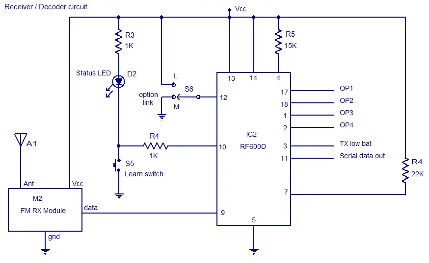
The decoder system comprises of the IC2 RF600D and its associated components. Pins 17, 18, 1 and 2 are the digital data output pins of RF600D corresponding to the input switches S1 to S4 of the encoder/transmitter circuits. The digital data output pins 17,18,1 and 2 are asserted low when the relevant inputs S1 to S4 on the IC2 RF600E are asserted. M2 is a general purpose FM receiver module which receives the transmitted code and feds it to the data input (pin 9) of the IC2. Switch S1 can be used to select between latching and momentary digital output function. In latching mode digital output pins (OP1 to OP4) are only asserted for the corresponding transmit signal. In latching mode the output state is changed on each corresponding transmit signal. The learn switch S5 is used to enter the decoder IC in to the “learn mode”. Learn operation using push button switch S5 is as follows. 1) Press and release the push button switch S5. 2) The status LED D2 will glow when S5 is pressed and will remain ON when S5 is released. 3) Operate the encoder/transmitter once. 4) The status LED D2 will become OFF. 5) Operate the encoder/transmitter again. 6) The status LED will start flashing. 7) When the flashing of status LED stops, the encoder will be successfully taught to the decoder and the transmitter/encoder will now operate the receiver/decoder system. Up to seven encoder/transmitters can be learnt to each RF600D.Pin 3 of IC2 is the transmitter low battery indicator output and pin 11 is the serial data output.
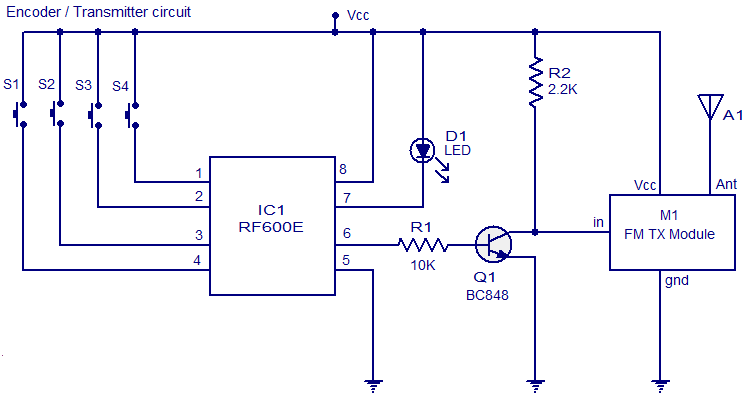

Circuit diagram.


FM remote encoder circuit 


FM remote decoder circuit


Notes.
  • Assemble the circuit on a good quality PCB.
  • The ICs can be operated from anything between 2V to 6.6V.
  • Switches S1 to S5 are miniature push button switches.
  • S6 can be a miniature two way switch.
  • Transmit LED D1 will glow whenever the encoder is transmitting.
  • The power supply must be properly regulated and ripple free.
  • I recommend using batteries for powering the circuit.
  • Go through the datasheets of RF600E and RF600D before attempting this circuit.
5 channel radio remote control

No comments:

TX-2B / RX / 2B  5 channel radio remote control.

This article is about a simple 5 channel radio remote control circuit based on ICs TX-2B and RX-2B from Silan Semiconductors. TX-2B / RX-2B is a remote encoder decoder pair that can be used for remote control applications. TX-2B / RX-2B has five channels, wide operating voltage range (from 1.5V to 5V), low stand by current (around 10uA), low operating current (2mA), auto power off function and requires few external components. The TX-2B / RX-2B was originally designed for remote toy car applications, but they can be used for any kind of remote switching application.

Circuit diagrams and description.

Remote encoder / transmitter circuit.

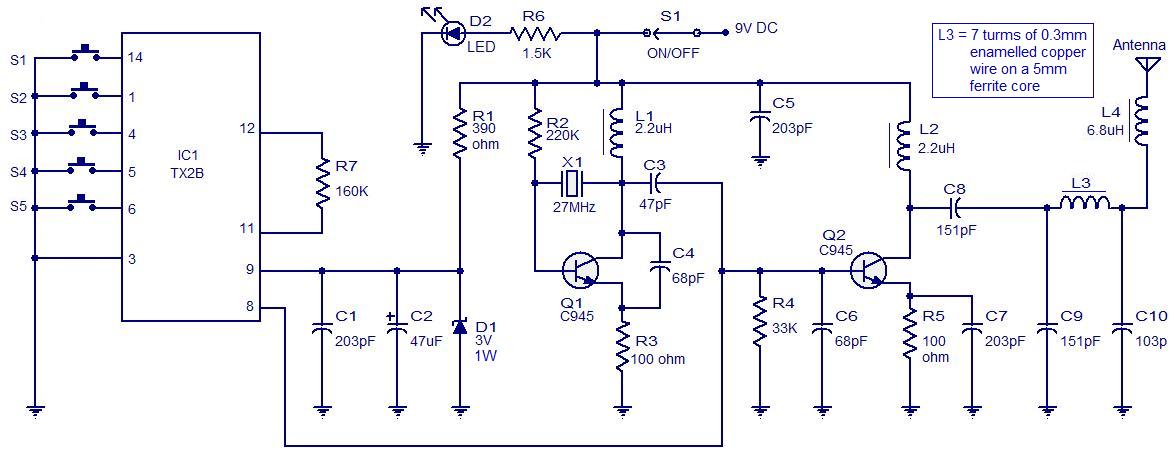
radio remote control transmitter ciruit
5 channel redio remote control encoder / transmitter circuit
The TX-2B forms the main part of the circuit. Push button switches S1 to S5 are used for activating (ON/OFF) the corresponding O/P channels in the receiver / decoder circuit. These push button switches are interfaced to the built-in latch circuitry of the TX-2B. Resistor R7 sets the frequency of the TX-2B’s internal oscillator. Resistor R1 and Zener diode D1 forms a simple Zener regulator circuit for providing the IC with 3V from the 9V main supply. C2 is the filter capacitor while C1 is a noise by-pass capacitor. D2 is the power on indicator LED while R6 limits the current through the same LED. S1 is the ON/OFF switch. The encoded control signal will be available at pin 8 of the IC. The encoded signal available at pin 8 is without carrier frequency. This signal is fed to the next stage of the circuit which is a radio transmitter. Crystal X1 sets the oscillator frequency of the transmitter section. R2 is the biasing resistor for Q1 while R3 limits the collector current of Q1. The encoded signal is coupled to the collector of Q1 through C3 for modulation. Transistor Q2 and associated components provide further amplification to the modulated signal.

Remote receiver / decoder circuit.

5 channel radio remote decoder

The remote receiver circuit is built around the IC RX-2B. The first part of the circuit is a radio receiver built around transistor Q1. The received signal is demodulated and fed to pin 14 of the IC. Pin 14 is the input of the built in inverter inside the IC. R2 sets the frequency of the IC’s internal oscillator. O/P 1 to O/5 are the output pins that are activated corresponding to the push buttons S1 to S5. Zener diode D1 and resistor R12 forms an elementary Zener regulator for supplying the RX-2B with 3V from the 9V main supply. C12 is the filter capacitor while R11 is the current limiter for the radio receiver section. Diode D2 protects the circuit from accidental polarity reversals. C15 is another filter capacitor and C14 is a noise by-pass capacitor.

Notes.

  • This circuit can be assembled on a vero board or a PCB.
  • Use 9V DC for powering the transmitter / receiver circuits.
  • Battery is the better option for powering the transmitter / receiver circuit.
  • If you are using a DC power supply circuit, it must be well regulated and free from any sort of noise.
  • Both ICs must be mounted on holders.

Interfacing relay to the RX-2B output.

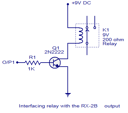
The method for interfacing a relay to the output of RX-2B is shown below. When push button switch S1 of the transmitter circuit is pressed, pin O/P1 (pin 7 of the RX-2B) goes high. This makes the transistor 2N2222 to conduct and the relay is activated. The same technique can be applied to other output pins of the RX-2B. The relay used here is a 200 ohm type and at 9V supply voltage the load current will be 45mA which is fine for 2N2222 whose maximum possible collector current is 900mA. When using relays of other ratings this point has to be remembered and do not use a relay that consumes a current more than the maximum possible collector current of the driver transistor.
transistor relay driver
Interfacing relay to the remote decoder


Thursday, November 21, 2013

Radio Remote Control Using DTMF

No comments:
click the image to enlarge…

Here is a circuit of a remote control unit which makes use of the radio frequency signals to control various electrical appliances. This remote control unit has 4 channels which can be easily extended to 12. This circuit differs from similar circuits in view of its simplicity and a totally different concept of generating the control signals. Usually remote control circuits make use of infrared light to transmit control signals. Their use is thus limited to a very confined area and line-of-sight. However, this circuit makes use of radio frequency to transmit the control signals and hence it can be used for control from almost anywhere in the house. Here we make use of DTMF (dual-tone multi frequency) signals (used in telephones to dial the digits) as the control codes. The DTMF tones are used for frequency modulation of the carrier. At the receiver unit, these frequency modulated signals are intercepted to obtain DTMF tones at the speaker terminals. This DTMF signal is connected to a DTMF-to-BCD converter whose BCD output is used to switch-on and switch-off various electrical applicances (4 in this case). The remote control transmitter consists of DTMF generator and an FM transmitter circuit. For generating the DTMF frequencies, a dedicated IC UM91214B (which is used as a dialler IC in telephone instruments) is used here. This IC requires 3 volts for its operation. This is provided by a simple zener diode voltage regulator which converts 9 volts into 3 volts for use by this IC. For its time base, it requires a quartz crystal of 3.58 MHz which is easily available from electronic component shops. Pins 1 and 2 are used as chip select and DTMF mode select pins respectively. When the row and column pins (12 and 15) are shorted to each other, DTMF tones corresponding to digit 1 are output from its pin 7. Similarly, pins 13, 16 and 17 are additionally required to dial digits 2, 4 and 8. Rest of the pins of this IC may be left as they are. The output of IC1 is given to the input of this transmitter circuit which effectively frequency modulates the carrier and transmits it in the air. The carrier frequency is determined by coil L1 and trimmer capacitor VC1 (which may be adjusted for around 100MHz operation). An antenna of 10 to 15 cms (4 to 6 inches) length will be sufficient to provide adequate range. The antenna is also necessary because the transmitter unit has to be housed in a metallic cabinet to protect the frequency drift caused due to stray EM fields. Four key switches (DPST push-to-on spring loaded) are required to transmit the desired DTMF tones. The switches when pressed generate the specific tone pairs as well as provide power to the transmitter circuit simultaneously. This way when the transmitter unit is not in use it consumes no power at all and the battery lasts much longer. The receiver unit consists of an FM receiver (these days simple and inexpensive FM kits are readily available in the market which work exceptionally well), a DTMF-to-BCD converter and a flip-flop toggling latch section. The frequency modulated DTMF signals are received by the FM receiver and the output (DTMF tones) are fed to the dedicated IC KT3170 which is a DTMF-to-BCD converter. This IC when fed with the DTMF tones gives corresponding BCD output; for example, when digit 1 is pressed, the output is 0001 and when digit 4 is pressed the output is 0100. This IC also requires a 3.58MHz crystal for its operation. The tone input is connected to its pin 2 and the BCD outputs are taken from pins 11 to 14 respectively. These outputs are fed to 4 individual �D� flip-flop latches which have been converted into toggle flip-flops built around two CD4013B ICs. Whenever a digit is pressed, the receiver decodes it and gives a clock pulse which is used to toggle the corresponding flip-flop to the alternate state. The flip-flop output is used to drive a relay which in turn can latch or unlatch any electrical appliance. We can upgrade the circuit to control as many as 12 channels since IC UM91214B can generates 12 DTMF tones. For this purpose some modification has to be done in receiver unit and also in between IC2 and toggle flip-flop section in the receiver. A 4-to-16 lines demultiplexer (IC 74154) has to be used and the number of toggle flip-flops have also to be increased to 12 from the existing 4.

--------------------------------------------------------------------------------------------------------------