RTC using Ds1307 and 89c52 with Multiplex 7-segment display
Salam ....Friends in this tutorial ,we are interfacing real time clock Ds1307 with 89c52 and displaying time on multiplex 7-segment display .In google there are many related projects about the Real Time Clock but no one use the 7-segment display so my method is different and less expensive ,because i don't use the crystal LCD. step1 is about RTC and I2c .
RTC is an electronic device which plays an essential role in realtime embedded system design.
It provides a precise time and date in various applications such as
system clock, student attendance system and alarm etc, that keep track
on current time and provides consistent result to the respective task.
This article presents RTC interfacing with 8051microcotrollerand basic
accessing of internal registers.
RTC Programming and Interfacing
RTC interfacing with 89c52
microcontroller is similar to all other kinds of “Real Time Clocks”
interfaced to it. So let us look on simple RTC interfacing with 89c52 microcontroller and programming procedure involving in it.
Step1: Select RTC Device
The various kinds of RTC chips are
available in the real time embedded world, which are classified based on
various criteria such as package type, supply voltage and pin
configuration etc. A few types of RTC devices are;
- Two-Wire Serial Interface (I2C Bus)
- Three-Wire Serial Interface (USB BUS)
- Four-wire Serial interface (SPI BUS)
First, we need to select type of RTC
device by category based on requirement like I2C Bus RTC or SPI Bus RTC
or other, which suitsfor interfacingwith respective microcontroller.
Then we can select features of RTC device depending on requirement of
application such as battery life, suitable package and clock frequency.
Let us consider two-wire interfacing RTC with 8051 microcontroller such as DS1307.
Step2: Internal Register and Address of the RTC Device
RTC stands for real time clock which
provides years, months, weeks, days, hours, minutes and seconds based on
crystal frequency. RTC consists of inbuilt RAM memory for data storage. A battery backup will be provided in case of failure of main power supply by connecting a battery to RTC device.
RTC DB1307 Configuration:
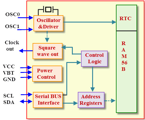
RTC Internal Blocks and Pin Diagram
A0, A1, A2: are address
pins of RTC DB1307 chip, which can be used to communicate with the
master device. We can control eight devices with RTC interfacing with 89c52 microcontroller by A0, A1, A2 bits using I2C protocol.
VCC and GND: VCC and GND are power supply and ground pins respectively. This device operated with 1.8V to 5.5V range.
VBT: VBT is a battery power supply pin. Battery power source must be held between 2V to 3.5V.
SCL: SCL is a serial clock pin and it is used to synchronize data on serial interface.
SDL: It is a serial input and output pin. It is used to transmit and receive the data on serial interface.
Clock Out: It is an optional square wave output pin.
OSC0 and OSC1: These
are crystal oscillator pins which are used to provide the clock signals
to the RTC device. The standard quartz crystal frequency is 22.768KHzs.
Device Addressing:
I2C bus protocol allows many slave
devices at a time. Every slave device must consist of own address to
represent on it. The master device communicates with particular slave
device by an address. RTC device address is “0xA2” wherein “1010” is
given by manufacturer and A0, A1, A2 are user define address, which is
used to communicate eight RTC devices on the I2C bus protocol.
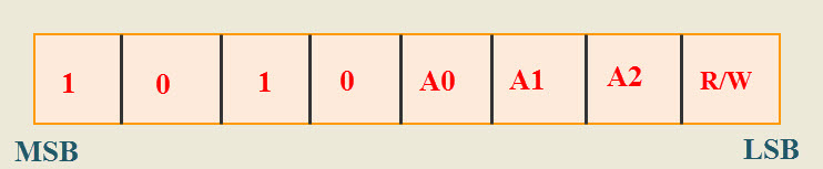
Device Addresing
R/W bit is used to perform read and
write operations in RTC. If R/W=0, write operation is performed and
R/W=1 for read operation.
Address of Read operation of RTC= “0xA3”
Address of Write operation of RTC= “0xA2”
Memory Registers and Address:
RTC registers are located in address
locations from 00h to 0Fh and RAM memory registers are located in
address locations from 08h to3Fh as shown in figure. RTC registers are
used to provide calendar functionality and drive time of day and to
display the weekends.
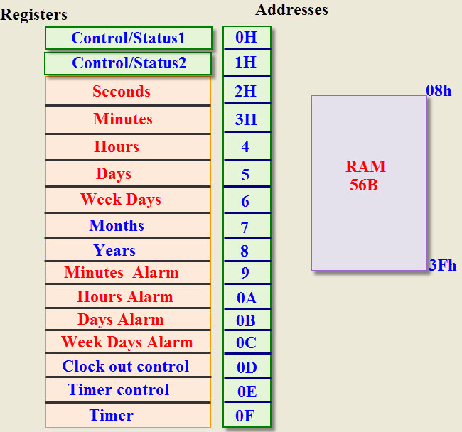
Memory Registers and Address
Control/Status Registers:
DB1307 consists of two additional
registers such as control/status1 and control/status2 which are used to
control real time clock and interrupts.
Control/Status Register1:
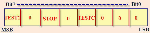
Control Status Register1
- TEST1=0 normal mode
=1 EXT-clock test mode
- STOP=0 RTC starts
=1 RTC stop
- TESTC=0 power on reset disabled
= power on reset enabled
Control/Status Register2:
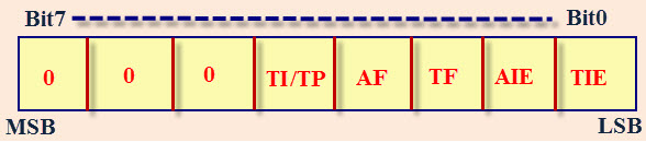
Control Status Register2
- TI/TP= 0 INT active all the time
=1 INT active required time
- AF=0 Alarm does not match
=1 Alarm match
- TF=0 Timer overflow does not occur
=1 Timer overflow occurs
- ALE=0 Alarm interrupts disable
=1 Alarm interrupts enabled
- TIE=0 Timer interrupts disable
=1 Timer interrupts enable
Step3: Interfacing RTC ds1307 with 89c52
RTC can be interfaced to microcontroller by using different serial bus protocols such as I2C and SPI protocols
that provide communication link between them. The figure shows, real
time clock interfacing with 89c52/8051 microcontroller using I2C bus protocol.
I2C is a bi-directional serial protocol, which consist of two wires
such as SCL and SDA to transfer data between devices connected to bus.
89c52 microcontroller has no inbuilt RTC device therefore we have
connected externally through a serial communication for ensuring the consisting data.

I2C devices have open drain outputs therefore, a pull-up resistors
must be connected to the I2C bus line with a voltage source. If the
resistors are not connected to the SCL and SDL lines, the bus will not
work.
Step4: RTC Data Framing Format
Since RTC interfacing with 89c52
microcontroller uses I2C bus therefore the data transfer is in the form
of bytes or packets and each byte is followed by an acknowledgement.
Transmitting Data Frame:
In transmitting mode, the master release
the start condition after selecting slave device by address bit. The
address bit contains 7-bit, which indicate the slave devices as ds1307
address. Serial data and serial clock are transmitted on SCL and SDL
lines. START and STOP conditions are recognized as beginning and ending
of a serial transfer. Receive and transmit operations are followed by
the R/W bit.
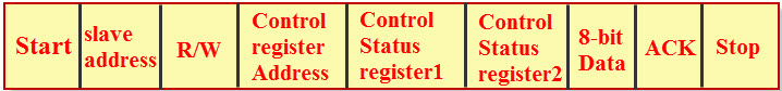
Transmitting Data Frame
Start: Primarily, the data transfer sequence initiated by the master generating the start condition.
7-bit Address: After that the master sends the slave address in two 8-bit formats instead of a single 16-bit address.
Control/Status Register Address: The control/status register address is to allow the control status registers.
Control/Status Register1: The control status register1 used to enable the RTC device
Control/Status Register2: It is used to enable and disable interrupts.
R/W: If read and write bit is low, then the write operation is performed.
ACK: If write operation is performed in the slave device, then the receiver sends 1-bit ACK to microcontroller.
Stop: After completion of write operation in the slave device, microcontroller sends stop condition to the slave device.
Receiving Data Frame:
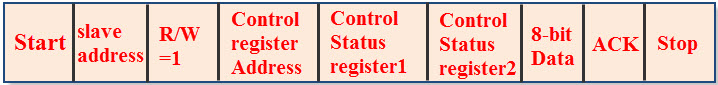
Receiving Data Frame
Start: Primarily, the data transfer sequence initiated by the master generating the start condition.
7-bit Address: After that the master sends slave address in two 8-bit formats instead of a single 16-bit address.
Control/Status Register Address: The control/status register address is to allow control status registers.
Control/Status Register1: The control status register1 used to enable the RTC device
Control/Status Register2: It is used to enable and disable interrupts.
R/W: If read and write bit is high, then the read operation is performed.
ACK: If write operation is performed in the slave device, then the receiver sends 1-bit ACK to microcontroller.
Stop: After completion of write operation in the slave device, microcontroller sends stop condition to the slave device.
Step5: RTC Programming
Write Operation from Master to Slave:
- Issue the start condition from master to slave
- Transfer the slave address in write mode on SDL line
- Send the control register address
- Send the control/status register1value
- Send the control/status register2 value
- Send the date of the like minutes, seconds and hours
- Send the stop bit
Coding :
MAIN CODE :
#include <AT89X52.h>
#define DS1307_ID 0xD0 // DS1307 ID
#define SEC_ADDRESS 0x00 // Address to access Ds1307 SEC register
#define DATE_ADDRESS 0x04 // Address to access Ds1307 DATE register
#define CONTROL 0x07 // Address to access Ds1307 CONTROL register
#define DELAY 1000
sbit seg_1= P2^0;
sbit seg_2= P2^1;
sbit seg_3= P2^2;
sbit seg_4= P2^3;
sbit SCL=P1^0; //SCL Connected to P1.0
sbit SDA=P1^1; //SDA Connected to P1.1
sbit mode = P2^4;
sbit set_low = P2^5;
sbit set_high = P2^6;
extern void delay_sec(unsigned char sec_count);
extern void delay_ms(unsigned int ms_count);
extern void delay_for_segments(unsigned int ms_count);
extern void delay_us(unsigned int us_count);
extern void delay_us_seg(unsigned int us_count);
extern void I2C_Clock(void);
extern void I2C_Start();
extern void I2C_Stop(void);
extern void I2C_Write(unsigned char dat);
extern unsigned char I2C_Read(void);
extern void I2C_Ack();
extern void I2C_NoAck();
extern void DS1307_Init();
extern void DS1307_Write(unsigned char dat);
extern unsigned char DS1307_Read();
extern void DS1307_SetTime(unsigned char hh, unsigned char mm, unsigned char ss);
extern void DS1307_SetDate(unsigned char dd, unsigned char mm, unsigned char yy);
extern void DS1307_GetTime(unsigned char *h_ptr,unsigned char *m_ptr,unsigned char *s_ptr);
extern void DS1307_GetDate(unsigned char *d_ptr,unsigned char *m_ptr,unsigned char *y_ptr);
unsigned char hex2bcd (unsigned char x);
unsigned char bcd_value;
unsigned char hour,min,sec,year,month,date,set_h,set_m,set_s,set_d,set_mon,set_y,blank=11;
unsigned char hour_tens,min_tens,sec_tens,month_tens,year_tens,date_tens;
const unsigned char bcd_to_segment[12]={0xC0,0xF9,0xA4,0xB0,0x99,0x92,0x82,0xF8,0x80,0x90,0x7F,0xFF};
unsigned char D1,D2,D3,D4;
enum states {
SHOW_TIME,
SHOW_DATE,
SHOW_YEAR,
SETL_TIME,
SETH_TIME,
SET_DATE,
SET_YEAR
};
void timer2() interrupt 5
{
seg_1=0;
seg_2=0;
seg_3=0;
seg_4=0;
delay_ms(1);
P0 = bcd_to_segment[D1];
seg_1 = 1;
delay_us(DELAY);
seg_1 = 0;
delay_ms(1);
P0 = bcd_to_segment[D2];
seg_2 = 1;
delay_us(DELAY);
seg_2 = 0;
delay_ms(1);
P0 = bcd_to_segment[D3];
seg_3 = 1;
delay_us(DELAY);
seg_3 = 0;
delay_ms(1);
P0 = bcd_to_segment[D4];
seg_4 = 1;
delay_us(DELAY);
seg_4 = 0;
delay_ms(1);
TF2=0; //clear Timer2 flag
} // interrupt closed
/*
void timer0(void) interrupt 1
{
}
void ISR_ex0(void) interrupt 0
{
led=0;delay_sec(1);led=1;
}*/
void main()
{
enum states state = SHOW_TIME;
D1 = D2 = D3 = D4 = 0;
RCAP2L = 0x30; // lower value
RCAP2H = 0xf8; // Specific values for 10ms
ET2 = 1;
/*TMOD=0x01;
TH0=0x18;
TL0=0xfc;
TR0=1;
ET0=1;
//IE0=1;
*/
set_h=0x12,set_m=0x11,set_s=0x00,set_d=0x17,set_mon=0x01,set_y=0x15; // setting time
DS1307_Init();
DS1307_SetTime(set_h,set_m,set_s);
DS1307_SetDate(set_d,set_mon,set_y);
set_low = 1;
set_high = 1;
mode = 1;
TR2 = 1;
EA = 1;
while(1)
{
DS1307_GetTime(&hour,&min,&sec);
sec_tens = sec & 0x0F;
sec = sec >> 4 ;
min_tens = min & 0x0F;
min = min >> 4 ;
hour_tens = hour & 0x0F;
hour = hour >> 4 ;
DS1307_GetDate(&date,&month,&year);
date_tens = date & 0x0F;
date = date >> 4 ;
month_tens = month & 0x0F;
month = month >> 4 ;
year_tens = year & 0x0F;
year = year >> 4 ;
switch(state)
{
case SHOW_TIME:
D1=hour;D2=hour_tens;D3=min;D4=min_tens;
if(set_low==0) // if the lower buuton is pressed
{
set_h++; // then after some delay , increment the hour
hex2bcd(set_h); // convert the hex value into bcd value
if(set_h<=12) // this is check for hours
DS1307_SetTime(bcd_value,set_m,set_s); // now the hour is updated with return bcd value
else set_h=0; // if values (hour value greater than 12 then hour=00 )
}
if(set_high==0) // if the higer button is pressed
{
set_m++; // then after some delay , increment the hour
hex2bcd(set_m); // convert the hex value into bcd value
if(set_m<=59) // check for mints
DS1307_SetTime(set_h,bcd_value,set_s); // now the mints is updated with return bcd value
else set_m=0; // if mins greater than 59 then makes mints =00
}
if(mode==0)
{
state = SHOW_DATE;
}
break;
case SHOW_DATE:
D1=date;D2=date_tens;D3=month;D4=month_tens;
if(set_low==0) // if the lower buuton is pressed
{
set_d++; // then after some delay , increment the date
hex2bcd(set_d); // convert the hex value into bcd value
if(set_d<=30)
DS1307_SetDate(bcd_value,set_mon,set_y); // now the date is updated with return bcd value
else set_d=0;
}
if(set_high==0) // if the higher buuton is pressed
{
set_mon++; // then after some delay , increment the month
hex2bcd(set_mon); // convert the hex value into bcd value
if(set_mon<=12)
DS1307_SetDate(set_d,bcd_value,set_y); // now the month is updated with return bcd value
else set_mon=0;
}
if(mode==0)
{
state = SHOW_YEAR;
}
break;
case SHOW_YEAR:
D1=2;D2=0;D3=year;D4=year_tens;
if(set_high==0) // if the higer buuton is pressed
{
set_y++; // then after some delay , increment the year
hex2bcd(set_y); // convert the hex value into bcd value
if(set_y<=99)
DS1307_SetDate(set_d,set_mon,bcd_value); // now the year is updated with return bcd value
else set_y=0;
}
if(mode==0)
{
state = SHOW_TIME;
}
break;
} //switch close
} //while loop close
} // main close
unsigned char hex2bcd (unsigned char x)
{
bcd_value = (x / 10) << 4;
bcd_value = bcd_value | (x % 10);
return (bcd_value);
}Functions Used In RTC Code :
#include <AT89X52.h>
#define DS1307_ID 0xD0 // DS1307 ID
#define SEC_ADDRESS 0x00 // Address to access Ds1307 SEC register
#define DATE_ADDRESS 0x04 // Address to access Ds1307 DATE register
#define CONTROL 0x07 // Address to access Ds1307 CONTROL register
sbit seg_1= P2^0;
sbit seg_2= P2^1;
sbit seg_3= P2^2;
sbit seg_4= P2^3;
sbit SCL=P1^0; //SCL Connected to P1.0
sbit SDA=P1^1; //SDA Connected to P1.1
void delay_sec(unsigned char sec_count);
void delay_ms(unsigned int ms_count);
void delay_us(unsigned int us_count);
void I2C_Clock(void);
void I2C_Start();
void I2C_Stop(void);
void I2C_Write(unsigned char dat);
unsigned char I2C_Read(void);
void I2C_Ack();
void I2C_NoAck();
void DS1307_Init();
void DS1307_Write(unsigned char dat);
unsigned char DS1307_Read();
void DS1307_SetTime(unsigned char hh, unsigned char mm, unsigned char ss);
void DS1307_SetDate(unsigned char dd, unsigned char mm, unsigned char yy);
void DS1307_GetTime(unsigned char *h_ptr,unsigned char *m_ptr,unsigned char *s_ptr);
void DS1307_GetDate(unsigned char *d_ptr,unsigned char *m_ptr,unsigned char *y_ptr);
void delay_sec(unsigned char sec_count)
{
while(sec_count!=0)
{
delay_ms(1000); //delay_ms is called to generate 1sec delay
sec_count--;
}
}
void delay_ms(unsigned int ms_count)
{
while(ms_count!=0)
{
delay_us(112); //delay_us is called to generate 1ms delay
ms_count--;
}
}
void delay_us(unsigned int us_count)
{
while(us_count!=0)
{
us_count--;
}
}
/*I2c Library .............................................................................*/
void I2C_Clock(void)
{
delay_us(1);
SCL = 1; // Wait for Some time and Pull the SCL line High
delay_us(1); // Wait for Some time
SCL = 0; // Pull back the SCL line low to Generate a clock pulse
}
void I2C_Start()
{
SCL = 0; // Pull SCL low
SDA = 1; // Pull SDA High
delay_us(1);
SCL = 1; //Pull SCL high
delay_us(1);
SDA = 0; //Now Pull SDA LOW, to generate the Start Condition
delay_us(1);
SCL = 0; //Finally Clear the SCL to complete the cycle
}
void I2C_Stop(void)
{
SCL = 0; // Pull SCL low
delay_us(1);
SDA = 0; // Pull SDA low
delay_us(1);
SCL = 1; // Pull SCL High
delay_us(1);
SDA = 1; // Now Pull SDA High, to generate the Stop Condition
}
void I2C_Write(unsigned char dat)
{
unsigned char i;
for(i=0;i<8;i++) // loop 8 times to send 1-byte of data
{
SDA = dat & 0x80; // Send Bit by Bit on SDA line
I2C_Clock(); // Generate Clock at SCL
dat = dat<<1;
}
SDA = 1; // Set SDA at last
}
unsigned char I2C_Read(void)
{
unsigned char i, dat=0x00;
SDA=1; //Make SDA as I/P
for(i=0;i<8;i++) // loop 8times to read 1-byte of data
{
delay_us(1);
SCL = 1; // Pull SCL High
delay_us(1);
dat = dat<<1; //dat is Shifted each time and
dat = dat | SDA; //ORed with the received bit to pack into byte
SCL = 0; // Clear SCL to complete the Clock
}
return dat; // Finally return the received Byte*
}
void I2C_Ack()
{
SDA = 0; //Pull SDA low to indicate Positive ACK
I2C_Clock(); //Generate the Clock
SDA = 1; // Pull SDA back to High(IDLE state)
}
void I2C_NoAck()
{
SDA = 1; //Pull SDA high to indicate Negative/NO ACK
I2C_Clock(); // Generate the Clock
SCL = 1; // Set SCL */
}
/*...............................1307 library ...............................*/
void DS1307_Init()
{
I2C_Start(); // Start I2C communication
DS1307_Write(DS1307_ID); // Connect to DS1307 by sending its ID on I2c Bus
DS1307_Write(CONTROL); // Select the Ds1307 ControlRegister to configure Ds1307
DS1307_Write(0x00); // Write 0x00 to Control register to disable SQW-Out
I2C_Stop(); // Stop I2C communication after initilizing DS1307
}
void DS1307_Write(unsigned char dat)
{
I2C_Write(dat); // Connect to DS1307 by sending its ID on I2c Bus
I2C_Clock();
}
unsigned char DS1307_Read()
{
unsigned char dat;
dat = I2C_Read(); // Connect to DS1307 by sending its ID on I2c Bus
return(dat);
}
void DS1307_SetTime(unsigned char hh, unsigned char mm, unsigned char ss)
{
I2C_Start(); // Start I2C communication
DS1307_Write(DS1307_ID); // connect to DS1307 by sending its ID on I2c Bus
DS1307_Write(SEC_ADDRESS); // Select the SEC RAM address
DS1307_Write(ss); // Write sec on RAM address 00H
DS1307_Write(mm); // Write min on RAM address 01H
DS1307_Write(hh); // Write hour on RAM address 02H
I2C_Stop(); // Stop I2C communication after Setting the Time
}
void DS1307_SetDate(unsigned char dd, unsigned char mm, unsigned char yy)
{
I2C_Start(); // Start I2C communication
DS1307_Write(DS1307_ID); // connect to DS1307 by sending its ID on I2c Bus
DS1307_Write(DATE_ADDRESS); // Request DAY RAM address at 04H
DS1307_Write(dd); // Write date on RAM address 04H
DS1307_Write(mm); // Write month on RAM address 05H
DS1307_Write(yy); // Write year on RAM address 06h
I2C_Stop(); // Stop I2C communication after Setting the Date
}
void DS1307_GetTime(unsigned char *h_ptr,unsigned char *m_ptr,unsigned char *s_ptr)
{
I2C_Start(); // Start I2C communication
DS1307_Write(DS1307_ID); // connect to DS1307 by sending its ID on I2c Bus
DS1307_Write(SEC_ADDRESS); // Request Sec RAM address at 00H
I2C_Stop(); // Stop I2C communication after selecting Sec Register
I2C_Start(); // Start I2C communication
DS1307_Write(0xD1); // connect to DS1307( under Read mode)
//by sending its ID on I2c Bus
*s_ptr = DS1307_Read(); I2C_Ack(); // read second and return Positive ACK
*m_ptr = DS1307_Read(); I2C_Ack(); // read minute and return Positive ACK
*h_ptr = DS1307_Read(); I2C_NoAck(); // read hour and return Negative/No ACK
I2C_Stop(); // Stop I2C communication after reading the Time
}
void DS1307_GetDate(unsigned char *d_ptr,unsigned char *m_ptr,unsigned char *y_ptr)
{
I2C_Start(); // Start I2C communication
DS1307_Write(DS1307_ID); // connect to DS1307 by sending its ID on I2c Bus
DS1307_Write(DATE_ADDRESS); // Request DAY RAM address at 04H
I2C_Stop(); // Stop I2C communication after selecting DAY Register
I2C_Start(); // Start I2C communication
DS1307_Write(0xD1); // connect to DS1307( under Read mode)
// by sending its ID on I2c Bus
*d_ptr = DS1307_Read(); I2C_Ack(); // read Day and return Positive ACK
*m_ptr = DS1307_Read(); I2C_Ack(); // read Month and return Positive ACK
*y_ptr = DS1307_Read(); I2C_NoAck(); // read Year and return Negative/No ACK
I2C_Stop(); // Stop I2C communication after reading the Time
}///////////// This project is created in Kielu vesion 4 ........thanksok friends if u have any problem in coding mail me Lcat215@gmail.com


pakistani chat rooms and Girls Mobile Numbers,
ReplyDeleteChat Room
chat Rooms
Pakistani chat rooms
Pakistani Girls mobile Numbers,
www.study.result.pk/
ReplyDelete